7
Operating manual
TROX air terminal units
Type VFC volume ow controllers
1
23
4
y
VFC
~
~
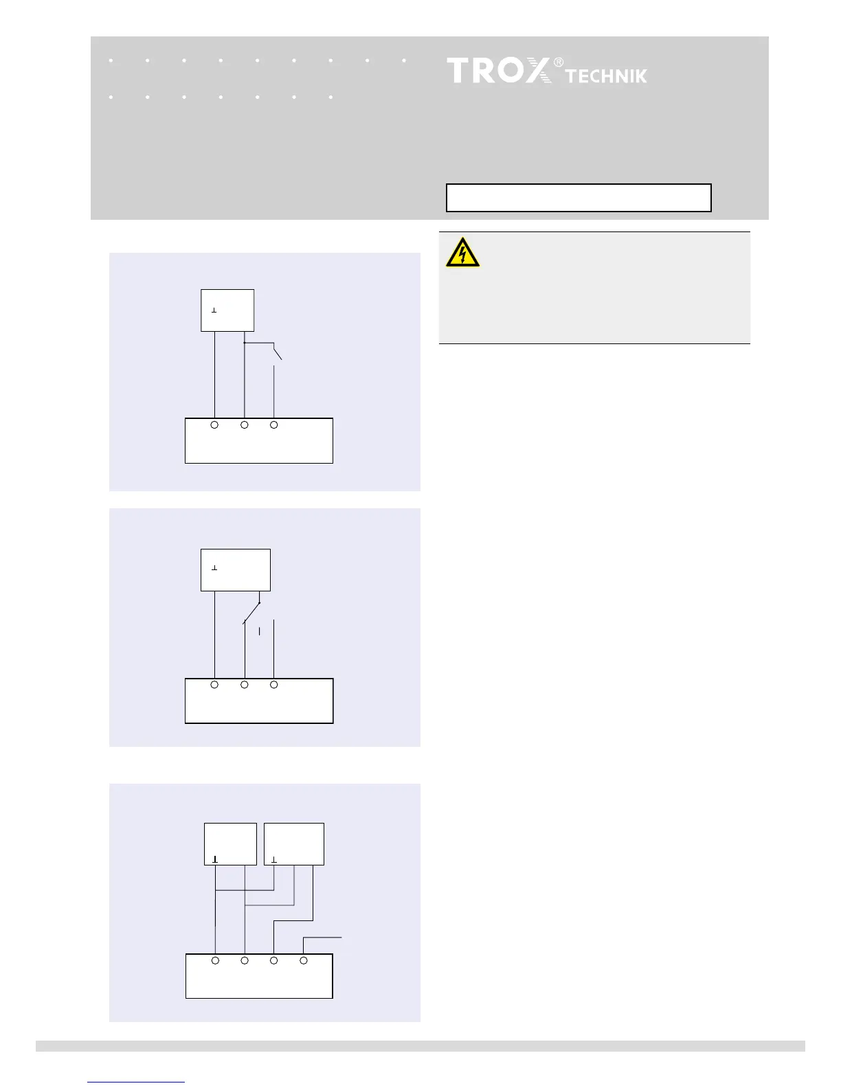
Continuous control input signal
Variable volume ow rate wiring
E03
24 V
Room temperature
controller
Actual value
output (value to
be set)
123
VFC
~
S1
E01, E02
24 V / 230 VAC
12
0
3
~
VFC
2
S2
3
2-wire control
min
/
max
24 V / 230 VAC
E01, E02
Danger!
Danger of electric shock! Do not touch any live
components! Electrical equipment carries
a dangerous electrical voltage.
• Only skilled qualified electricians are allowed
to work on the electrical system.
• Switch off the power supply before working on
any electrical equipment.
Actuator E01, E02
Electrical connection data:
E01: 24 V AC ±20% 50/60 Hz; 4 VA
24 V DC ±20% 2,5 W
E02: 230 V AC 50/60 Hz 4 VA
Switches provided by the customer (volt-free contacts) can
be used for making the switching procedures shown below:
1-wire control (illustration above)
Switch S1 open :
min
Switch S1 closed :
max
2-wire control (3-point) (illustration in middle)
Switch S2 at 0: Drive stopped
Switch S2 at 2:
min
Switch S2 at 3:
max
Actuator E03
Electrical connection data:
Supply:
24 V AC ±20% 50/60 Hz 4 VA
24 V DC ±20% 2,5 W
Control signal: 0-10 V DC Ra > 100 kohm
Actual value output: 0-10 V DC
Room temperature control
A dedicated room temperature controller or a DDC outstation
with 0-10 V DC output is connected with at least 2 wires
(terminals 1 and 3) as shown in the circuit diagram. If the
controllers are on the same supply voltage (24 V) make sure
that terminal 1 of the VFC is identical to the ground of the
control signal.
Note:
Override control
max
with 24 V DC at terminal 3.
1-wire control
min
/
max
min
-
max
switching wiring
~
- +
N L
~
- +
N L
- +
Actuator E01 ... E03