9
Operating manual
TROX air terminal units
Type VFC volume ow controllers
Danger!
Danger of electric shock! Do not touch any
live components! Electrical equipment carries
a dangerous electrical voltage.
• Only skilled qualified electricians are allowed
to work on the electrical system.
• Switch off the power supply before working
on any electrical equipment.
Electrical connection data:
M01: 24 V AC ±20% 50/60 Hz 1 VA
24 V DC ±20% 0,5 W
M02: 230 V AC 50/60 Hz 3 VA
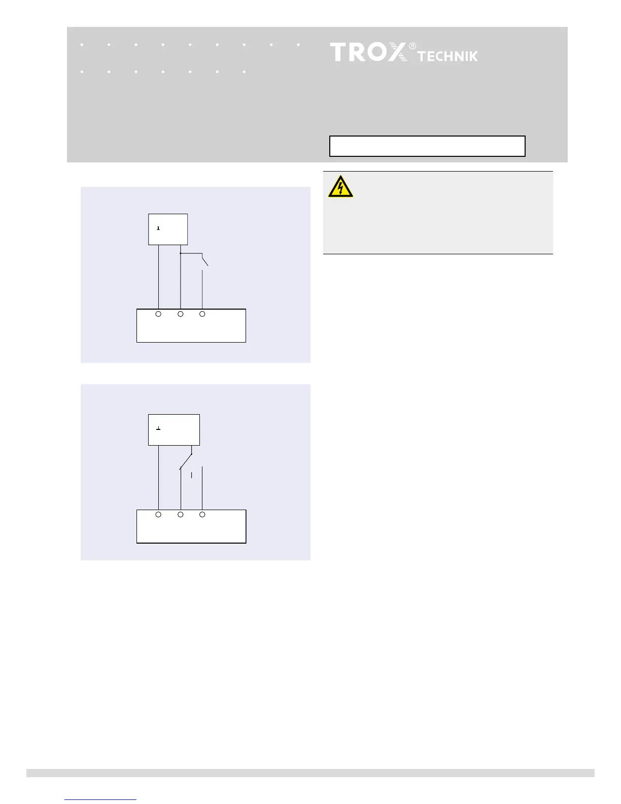
Switches provided by the customer (volt-free contacts) can
be used for making the switching procedures shown below:
1-wire control (illustration above)
Switch S1 open :
max
Switch S1 closed :
min
2-wire control (3-point) (illustration in middle)
Switch S2 at 0: Drive stopped
Switch S2 at 2:
max
Switch S2 at 3:
min
123
VFC
~
S1
12
0
3
~
VFC
2
S2
3
M01, M02
M01, M02
1-wire control
min
/
max
2-wire control (3-point)
min
/
max
min
-
max
switching wiring
24 V / 230 VAC
24 V / 230 VAC
~
- +
N L
~
- +
N L
Actuator M01 ... M02