8
Operating manual
TROX air terminal units
Type VFC volume ow controllers
Mechanical stop
for
min
Magnetic gear-
box disengage-
ment
Mechanical stop
for
max
Position indicator
with magnet
Variable volume ow control,
min
and
max
setting with mechanical stops
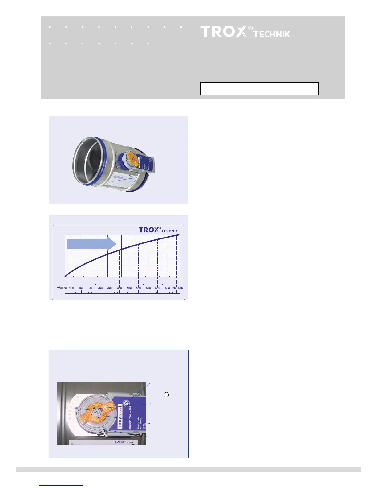
Characteristic for determining the volume ow rate
Set the set ow rate as follows:
• Determine the setting value for the set ow rate from the
characteristic or the table on page 5.
• Activate gearbox disengagement with magnet. The magnet
is integrated in the removable position indicator
• Make the corresponding settings on the mechanical stops.
• Deactivate gearbox disengagement again and reconnect the
position indicator, see also page 10.
Setting the set ow rate
Each VFC carries a characteristic to determine the setting
values on site (see example, nominal size 160).
min
settings below 3 results in an unregulated airow
dependent on the duct pressure that is not less than
min-unit
.
U
..
min
-
max
switching operation, actuator with
mechanical stops
Actuator M01 ... M02