I
Before inspecting, cleaning or servicing the machine, shut off engine, wait for all moving parts to ]
come to a stop, disconnectspark plug wire and move wire away from spark plug. Remove key on ]
electric start models. I
Failure to follow these instructionscan result in serious personal injury or property damage. I
11. Using a 9/16"wrench and a 7/32" hex
(Allen) wrench, loosenthe mounting nut
(G,Figure5-6) and screw on the idler
pulley (0 a few turns, or until belt is free
to slip out betweenpulley and belt guide
(J). Removebelt.
12. Loosenrear belt guide screw (K,
Figure5-6) enoughto allow belt to be
removedfrom engine pulley (L). Remove
belt from unit.
Belt Replacement
1. Install belt on engine pulley (L, Figure
5-6) and retighten rear beltguide screw
(K) securely.
2. Route belt betweenidler pulley (I,
Figure5-6) and belt guide (J), to inside of
brakearm (M), and nextto die-cast belt
guides (N).
3. Securelytighten the mounting nut (G,
Figure5-6) and screw in the idler pulley
0).
4. Securelytighten the idler arm
mounting screw (S, Figure 5-6). After
tightening, checkthat idler arm is freeto
rotate. If not, remove idler arm and check
for debris that may be interfering with
freedom of movement.
5. Lookat the spindlehead mounting
hole (O, Figure5-6) and note the grooves
that are cut into the inner sidesof the
hole= Thesegrooves wereformed by the
splines on the spindle shaft (E, Figure
5-5).
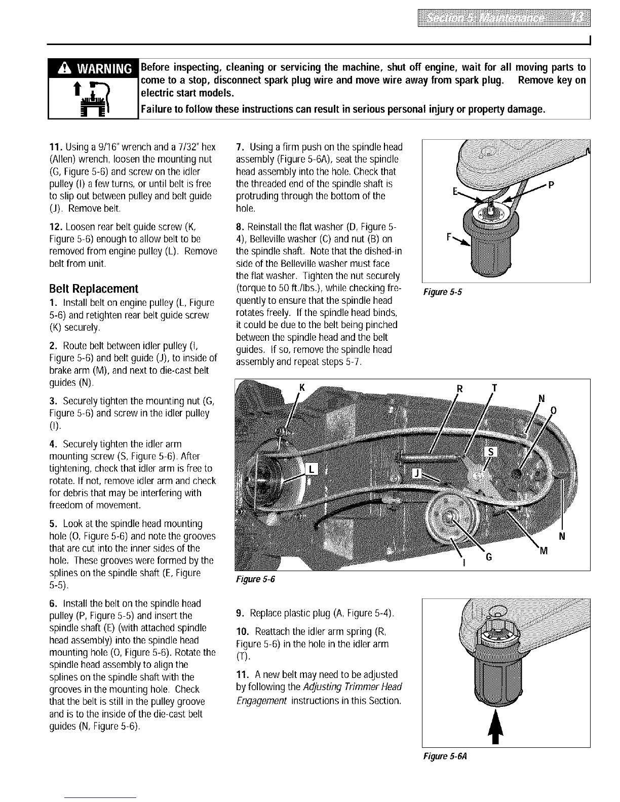
6. Installthe belt on the spindlehead
pulley (P, Figure5-5) and insert the
spindle shaft (E) (with attached spindle
headassembly) into the spindlehead
mounting hole (0, Figure 5-6). Rotatethe
spindle headassemblyto align the
splines on the spindle shaft with the
grooves in the mounting hole. Check
that the belt is still in the pulley groove
and is to the inside of the die-cast belt
guides (N, Figure5-6).
7. Using a firm push on the spindle head
assembly (Figure5-6A), seatthe spindle
headassembly into the hole.Checkthat
the threadedend of the spindle shaft is
protruding through the bottom of the
hole.
8. Reinstallthe flat washer (D, Figure5-
4), Bellevillewasher (C) and nut (B) on
the spindle shaft. Notethat the dished-in
sideof the Bellevillewasher must face
the flat washer. Tighten the nut securely
(torque to 50 ft./Ibs.), while checkingfre-
quently to ensure that the spindle head
rotatesfreely. If the spindle headbinds,
it could be due to the belt being pinched
betweenthe spindle headand the belt
guides. If so, remove the spindle head
assembly and repeatsteps5-7.
Figure 5-6
9. Replaceplastic plug (A,Figure5-4).
10. Reattachthe idler arm spring (R,
Figure5-6) in the hole in the idler arm
(T).
11. A new belt may needto be adjusted
byfollowing the Adjusting Trimmer Head
Engagement instructions in this Section.
Figure 5-5
R
Figure 5-6,4
T
6
N
0
N
 Loading...