Featuresand Controls
Various symbols (shown here,with
word descriptions) are used on the ENGINE FAST SLOW STOP TRIMMER ENGAGE
STOP HEAD BAIL
unit,
DISENGAGE
BAIL
Before operating your machine, care-
fully read and understand all safety,
controls and operating instructions in
this Manual, the separate Engine
Owner's Manual, and on the decals on
themachine.
Failure to follow these instructionscan
result inseriouspersonalinjury.
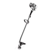
FEATURESAND CONTROLS
This Section describesthe location and
function of the features and controls on
your machine. Referto the following
OperationSectionfor detailedoperating
instructions.
IMPORTANT:Refer to the engine manual
for detailed information about the con-
trois on the engine.
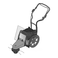
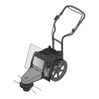
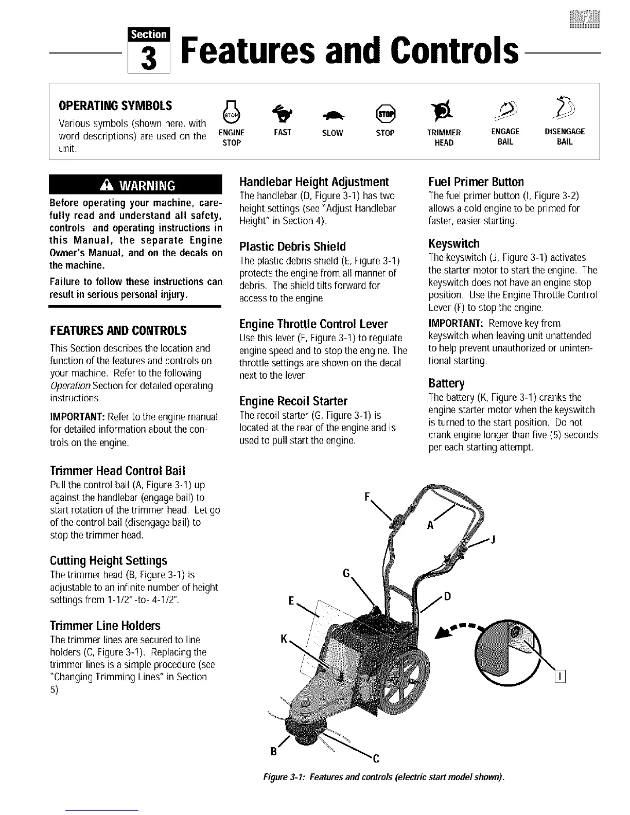
Trimmer Head Control Bail
Pull the control bail (A, Figure3-1) up
againstthe handlebar (engagebail) to
start rotation of the trimmer head. Let go
of the control bail (disengagebail) to
stop the trimmer head.
Cutting HeightSettings
Thetrimmer head (B, Figure 3-1) is
adjustableto an infinite number of height
settings from 1-1/2"-to- 4-1/2".
Trimmer Line Holders
Thetrimmer lines aresecured to line
holders (C, Figure3-1). Replacingthe
trimmer lines is a simple procedure (see
"ChangingTrimming Lines" in Section
5).
Handlebar Height Adjustment
Thehandlebar (D, Figure3-1) hastwo
height settings (see"Adjust Handlebar
Height" in Section4).
Plastic Debris Shield
Theplasticdebris shield (E, Figure 3-1)
protects the engine from all manner of
debris. Theshield tilts forward for
accessto the engine.
Engine Throttle Control Lever
Usethis lever (F, Figure 3-1) to regulate
enginespeedand to stop the engine.The
throttle settings are shown on thedecal
next to the lever.
Engine Recoil Starter
Therecoil starter (G, Figure3-1) is
locatedat the rear of the engine and is
usedto pull start the engine.
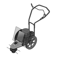
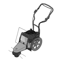
Fuel Primer Button
Thefuel primer button (I, Figure 3-2)
allows a cold engine to be primed for
faster, easierstarting.
Keyswitch
Thekeyswitch (J, Figure3-1) activates
the starter motor to start the engine. The
keyswitch does not havean engine stop
position. Usethe EngineThrottle Control
Lever(F) to stop the engine.
IMPORTANT:Removekey from
keyswitch when leavingunit unattended
to help prevent unauthorizedor uninten-
tional starting.
Battery
Thebattery (K,Figure 3-1) cranks the
enginestarter motor when the keyswitch
is turned to the start position. Donot
crank engine longer thanfive (5) seconds
per eachstarting attempt.
E_
K\
Figure3-1: Featuresand controls(electric startmodel shown).