Assembly
To prevent personal injury or property
damage, do not attempt to start the
engine until all assembly steps are
completeand you have read and under-
standall of thesafety and the operating
instructionsin thisManual.
INTRODUCTION
Carefullyfollow these assembly steps to
correctly prepareyour machinefor use.
It is recommendedthat you read this
Sectionin its entirety before beginning
assembly,
INSPECTIONAFTER DELIVERY
Inspectyour machine immediately after it
has beendelivered. Make surethat nei-
ther the carton nor the contents have
beendamaged.
If you find or suspect any damage,con-
tact the carrier (trucking company) right
away. Inform them of the specific
damageandthat you wish to file a claim.
To protect your rights, be sure to put this
in writing to the carrier within 15 days
after your machine arrives. Pleaselet us
know if you needassistance with this
matter.
IMPORTANT:Theengine is shipped
without motor oil in its crankcase.Motor
oil must beadded to the engine before
starting.
NOTE:LEFTand RIGHTsides of unit are
asviewed from operator's position
behindthe handlebars.
ASSEMBLY STEPS
Tools/SuppliesNeeded:
• (1) Utility Knifeor Scissors
• (2) 1/2" (or adjustable)Wrenches
• (2) 7/16" Wrenches (one with a boxed
end)
• Motor Oil (seeengine manualfor oil
specifications and quantity required)
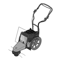
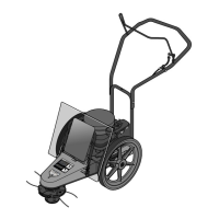
STEP 1: Unpack Unit
1. Removethe protective packaging
material (plastic film and cardboard) from
the handlebarsand the unit.
2. Removethe handlebarsfrom the insert
and carefully (do not pinch or kink the
attachedcables) putthem aside before
removing the unit from the shipping
carton.
3. Comparethe parts inside the carton
with the following list:
• MachineAssembly (A, Figure2-1)
• ExtraTrimmer Line (B, Figure 2-1): six
piecesof heavy-duty gauge .130"dia.
line and six piecesof extra-heavy-duty
gauge .155"dia. line.
• The following items are in a separate
package:
(3) Plastic cableties
(1) Hex Hd. Screw, 1t4-20 x 2
(1) Hex Locknut, 1/4-20
(2) Hex Hd. Screw, 5/16-18 x 2
(2) Hex Locknut, 5/16-18
• Electric Start Model Only:
(1) Battery (installed on unit - see
C, Figure2-1)
(2) Ignition Keysand (1) Battery
Recharger(in separateelectric
start package)
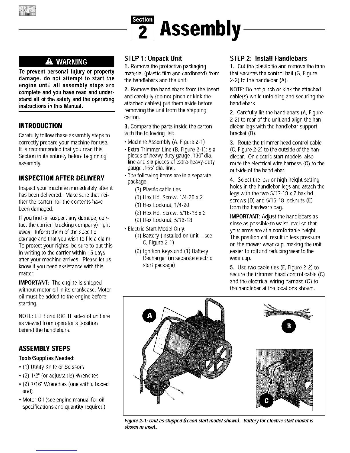
STEP 2: Install Handlebars
1. Cutthe plastic tie and remove the tape
that secures the control bail (G,Figure
2-2) to the handlebar (A).
NOTE:Do not pinch or kink the attached
cable(s)while unfolding and securing the
handlebars.
2. Carefullylift the handlebars(A, Figure
2-2) to rear of the unit and align the han-
dlebar legswith the handlebar support
bracket(B).
3. Routethe trimmer headcontrol cable
(C, Figure2-2) to the outside of the han-
dlebar. On electricstart models,also
routethe electricalwire harness(O) to the
outside ofthe handlebar.
4. Selectthe low or high height setting
holesin the handlebarlegs and attachthe
legswith the two 5/16-18 x 2 hex hd.
screws (D) and 5/16-18 Iocknuts (E)
from the hardware bag.
IMPORTANT:Adjust the handlebars as
close aspossible to waist levelso that
your arms are at a comfortable height.
This position will result in less pressure
on the mower wear cup, makingthe unit
easierto roll and reducingwearto the
wearcup.
5. Usetwo cableties (F, Figure 2-2) to
securethe trimmer headcontrol cable (C)
andthe electricalwiring harness (O)to
the handlebar at the locations shown.
O
Figure2* 1: Unitas shipped (recoil start model shown). Batteryfor electric start model is
shownin inset.