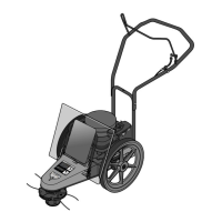
STEP 3: Attach Throttle Control
Lever
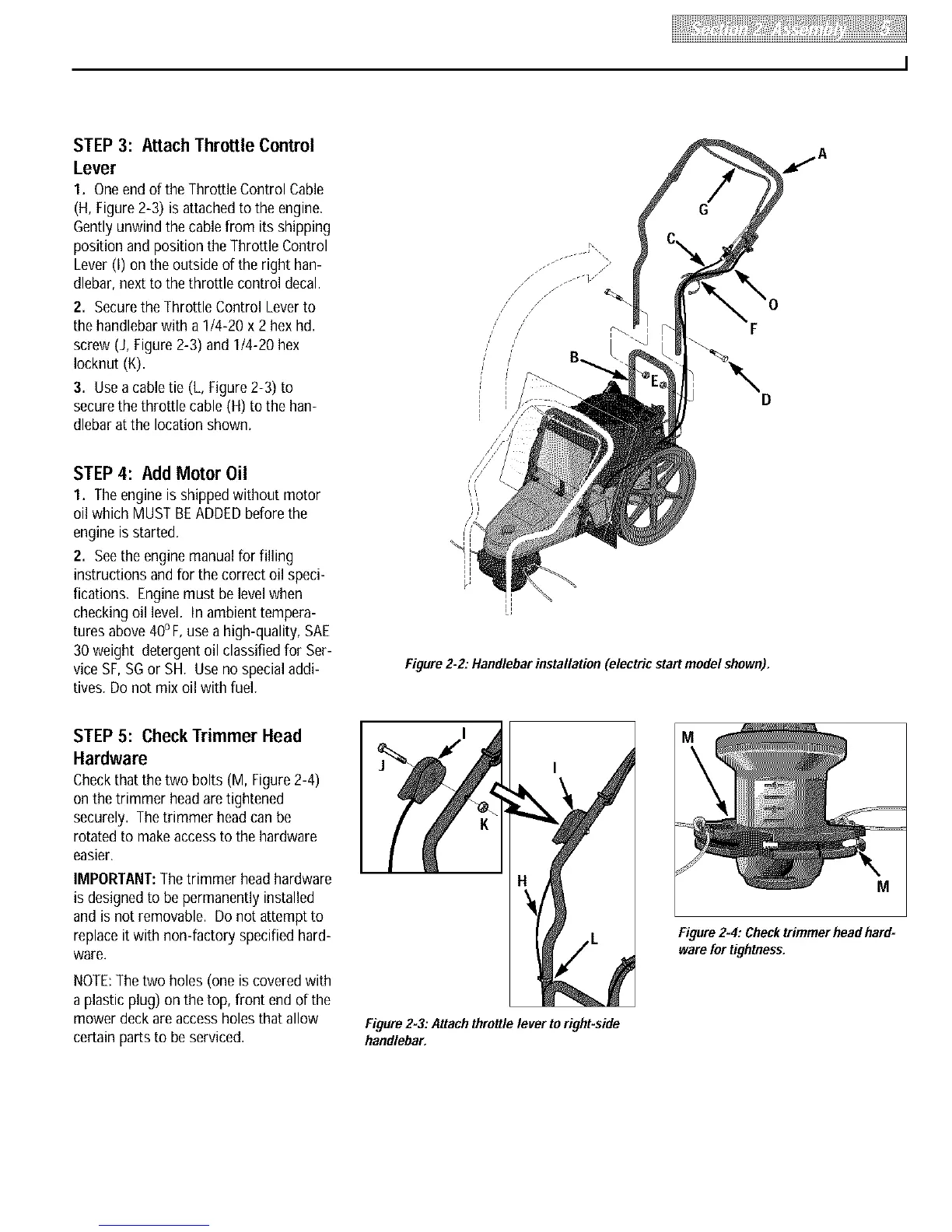
1. Oneendof the Throttle Control Cable
(H, Figure2-3) is attachedto the engine.
Gentlyunwind the cablefrom its shipping
position and position the Throttle Control
Lever(I) on the outside of the right han-
dlebar, next to the throttle control decal.
2. Securethe Throttle Control Leverto
the handlebarwith a 1t4-20 x 2 hex hd.
screw (J, Figure2-3) and 1t4-20 hex
Iocknut (K).
3. Usea cable tie (L, Figure2-3) to
securethethrottle cable (H) to the han-
dlebar at the location shown.
STEP 4: Add Motor Oil
1. Theengine is shippedwithout motor
oil which MUSTBEADDEDbefore the
engine is started.
2. Seethe engine manualfor filling
instructions andfor the correct oil speci-
fications. Enginemust be level when
checking oil level. In ambient tempera-
tures above 40oF,usea high-quality, SAE
30weight detergentoil classified for Ser-
vice SF,SGor SH. Useno specialaddi-
tives. Do not mix oil with fuel.
//
/
/
/
/
/
/
f
Figure 2-2."Handlebarinstallation (electric start model shown).
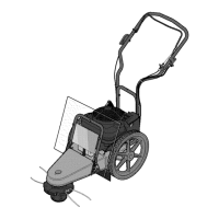
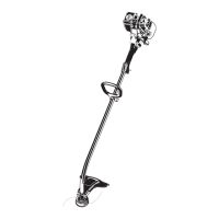
STEP 5: Check Trimmer Head
Hardware
Checkthat the two bolts (M, Figure 2-4)
on the trimmer headaretightened
securely. Thetrimmer headcanbe
rotatedto makeaccessto the hardware
easier.
IMPORTANT:Thetrimmer headhardware
is designedto be permanently installed
and is not removable. Do not attempt to
replaceitwith non-factory specified hard-
ware.
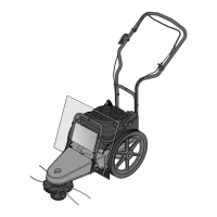
NOTE:Thetwo holes (one is covered with
a plastic plug) on the top, front end of the
mower deck areaccess holesthat allow
certain parts to beserviced.
I
I
Figure2-3."Attachthrottlelever to right-side
handlebar.
M
Figure2-4:Checktrimmerheadhard=
warefortightness.