4.
Before removing any further parts, inspect the condi-
tion ofthe flail cutting blades. Use a flashlight
to
exam-
ine them by looking into the service
door
opening
or
the discharge area opening. You'll
see
twofree-swinging
blades, separated
by
a spacer, on each
of
two
cylinder
pins.
A
DANGER
BEFORE
PERFORMING
THE
FOLLOWING
PROCEDURE, BE SURE
TO
DISCONNECTTHE
SPARK PLUG WIRE.
If any
of
the
four
blades is difficult
to
see, simply pull
out
the starter rope a little
to
cause the rotor/blade
assembly
to
turn - watch
your
fingers because the
shredder flail blades and the chipper blade are ex-
tremely sharp! While you're looking inside, inspect the
chipper
blade
for
nicksand cracks. Ifthe cutting edges
seem
to
be in
good
condition,
your
inspection
is
com-
plete. Refer
to
Photo 5-9. If one
or
more shredder
blades
is
worn
or
any spacers are damaged,
or
the
chipper blade mustbe removed, continue on with Step
5.
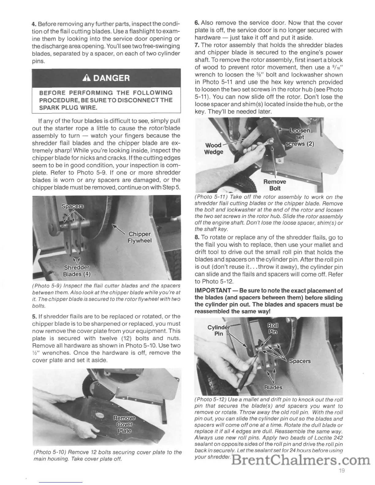
(Photo 5-9) Inspect the flail
cutter
blades
and
the spacers
between them.
Also
look
at
the
chipper
blade while you're at
it.
The
chipper
blade is secured to the
rotor
flywheel with two
bolts.
5.
If shredder flails are to be replaced
or
rotated,
or
the
chipper blade is to
be
sharpened
or
replaced, you must
now
remove the cover plate from
your
equipment. This
plate
is
secured with twelve
(12)
bolts and nuts.
Remove all hardware
as
shown in Photo 5-10. Use
two
1f2"
wrenches. Once the hardware
is
off, remove the
cover plate and set it aside.
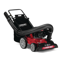
(Photo 5-10) Remove 12 boits securing cover plate to the
main housing.
Take
cover plate off.
6.
Also remove the service door.
Now
that the cover
plate
is
off, the service
door
is no longer secured with
hardware - just take it off and put it aside.
7.
The rotor assembly that holds the shredder blades
and
chipper
blade is secured
to
the engine's power
shaft. To remove the
rotor
assembly, first inserta block
of
wood
to
prevent rotor movement, then use a
9/
16
"
wrench
to
loosen the %" bolt and lockwasher shown
in Photo
5-11
and use the hex key wrench provided
to
loosen the
two
set screws in the
rotor
hub (see Photo
5-11). You can
now
slide
off
the rotor. Don't lose the
loose spacerand shim(s) located inside the hub,
orthe
key. They'll
be
needed later.
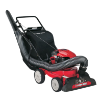
Remove
Bolt
(Photo
5-11)
Take
off
the
rotor
assembly to
work
on the
shredder flail
cutting
blades
or
the
chipper
blade. Remove
the
boit
and
lockwasher
at
the
end
of
the
rotor
and
loosen
the two set screws in the
rotor
hub. Slide the
rotor
assembly
off
the engine shaft.
Don't
lose the loose spacer, shim(s)
or
the shaft key.
8.
To rotate
or
replace any
of
the shredder flails,
go
to
the flail you wish
to
replace, then use
your
mallet and
drift tool
to
drive
out
the small roll pin that holds the
blades and spacers on the cylinder pin. Afterthe roll pin
is
out
(don't reuse it.
..
throw
it away), the
cylinder
pin
can slide and the flails and spacers will come off. Refer
to
Photo 5-12.
IMPORTANT- Be sure
to
notethe exact placement
of
the blades (and spacers between them) before sliding
the
cylinder
pin out. The blades and spacers must be
reassembled the same way!
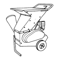
(Photo
5-12)
Use a mallet
and
drift
pin
to
knock
out
the
roll
pin
that secures the blade(s)
and
spacers
you
want
to
remove
or
rotate.
Throwaway
the
old
roll
pin. With the
roll
pin
out,
you
can slide the
cylinder
pin
out
so the blades
and
spacers
will
come
off
one
at
a time. Rotate the
dull
blade
or
replace
it
if
all 4 edges are dull. Reassemble the same way.
Always
use
new
roll
pins.
Apply
two beads
of
Loctite 242
sealant on oppositesides
of
the roll pin
and
drive the roll
pin
back
in securely. Letthe sealant set for 24 hoursbefore using
your
shredder.
19