Any blade that
is
worn on one corner can now be
turned end-to-end
or
just flipped over so a new cutting
edge
is
in position.
Or
replace the blade with a new one
if
all the cutting edges are dulled. Carefully reassemble
the flails and spacers on the cylinder pin. Apply Loctite
242 sealant to a new roll pin, then drive the roll pin back
in securely. Repeat this procedure if any of the blades
on the othercylinder pin need to
be
rotated or replaced.
Let the Loctite sealant cure for
24
hours before using
the shredder.
A CAUTION
CHIPPER BLADE IS EXTREMELY SHARP AND
CAN CAUSE PERSONAL INJURY.
AVOID CONTACT WITH THE BLADE EDGE.
HANDLE THE BLADE CAREFULLY.
9.
Now
is
the time
to
take
off
the chipper blade
if
it
needs sharpening
or
it's to
be
replaced with a new
blade. Be very careful not to cut yourself on this sharp
blade. Use a
W' wrench to take outthe two
5/
16
" -18 x %"
long Grade-8 bolts that secure it to the flywheel. The
hardened blade should
be
professionally sharpened at
a 45-degree angle. Install a new blade if the old one
is cracked
or
badly nicked. Tighten the hardware to
16-to-18 foot-pounds of torque when installing the
blade on the flywheel.
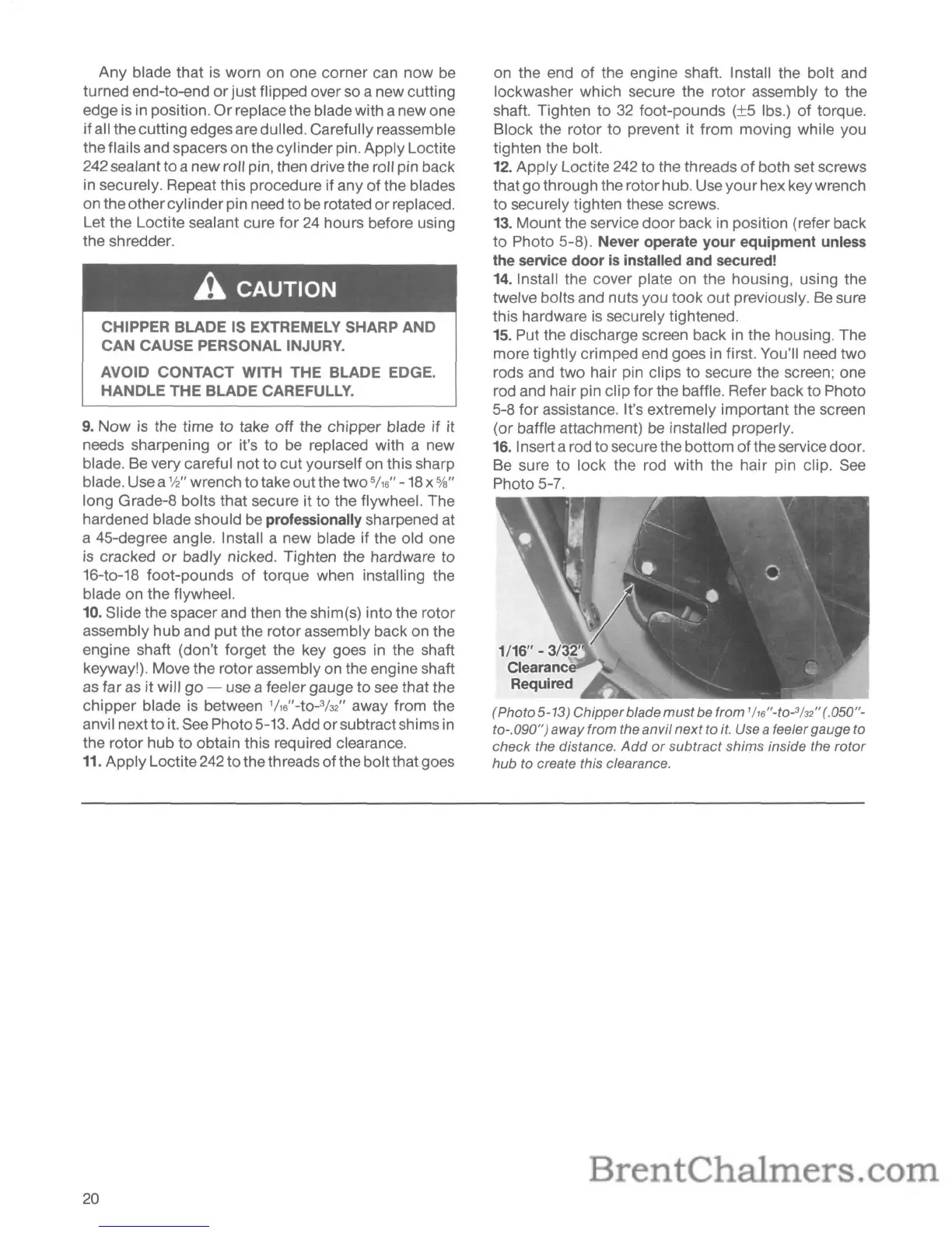
10. Slide the spacer and then the shim(s) into the rotor
assembly hub and put the rotor assembly back on the
engine shaft (don't forget the key goes
in
the shaft
keyway!). Move the rotor assembly on the engine shaft
as
far as it will
go
- use a feeler gauge to
see
that the
chipper blade
is
between
1/16"-tO-3h2"
away from the
anvil next to it.
See
Photo 5-13. Add orsubtract shims
in
the rotor hub to obtain this required clearance.
11.
Apply Loctite
242
to the th reads of the boltthat goes
20
on the end
of
the engine shaft. Install the bolt and
lockwasher which secure the rotor assembly to the
shaft. Tighten to
32
foot-pounds (±5 Ibs.) of torque.
Block the rotor to prevent it from moving while you
tighten the bolt.
12.
Apply Loctite
242
to the threads
of
both set screws
that go through the rotor hub. Use yourhex key wrench
to securely tighten these screws.
13. Mount the service door back
in
position (refer back
to
Photo 5-8). Never operate your equipment
unless
the
service
door
is
installed
and
secured!
14. Install the cover plate on the housing, using the
twelve bolts and nuts you took
out
previously.
Be
sure
this hardware
is
securely tightened.
15.
Put the discharge screen back in the housing. The
more tightly crimped end goes in first. You'll need two
rods and two hair pin clips to secure the screen; one
rod and hair pin clip for the baffle. Refer back to Photo
5-8 for assistance. It's extremely important the screen
(or baffle attachment)
be
installed properly.
16.
Inserta rod to secure the bottom ofthe service door.
Be
sure to lock the rod with the hair pin clip.
See
Photo 5-7.
(Photo 5-13) Chipperblade mustbe from
lh6
"-to-
3
h2
"(.050"-
to-.090") away from the anvilnext to
it.
Use a feeler gauge to
check the distance.
Add
or
subtract shims inside the
rotor
hub to create this clearance.