2
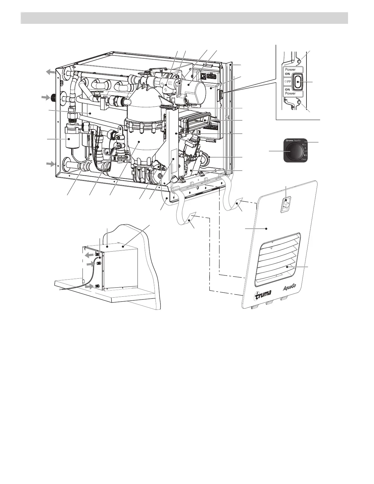
Overview / Designation of parts
Key
1 Cold water connection 1/2 in. NPT
2 Hot water connection 1/2 in. NPT
3 Circulation line connection 1/2in. NPT
(comfort plus model only)
4 Pressure relief valve
4a Test lever
5 Flue fan
6 Unit casing
7 Control unit
8 POWER switch
9 Latch
10 Flue duct
11 Easy Drain Lever
11a Water inlet filter
12 Gas pipe grommet (side)
13 Gas valve
14 Cover plate
15 Temperature stabilizer
16 Water flow sensor
17 Burner
18 Circulation pump (comfort and
comfort plus models)
19 Heat exchanger
20 Access door (assembly)
21 Turn lock
22 Webbing
23 Ventilation grille (air inlet, exhaust)
24 Grommet for 12 V cable (power supply)
25 Type plate
26 Exhaust pressure switch
27 Control panel
(comfort and comfort plus models)
LED 1 Power ON LED – green
LED 2 Error code LED – red
LED 3 Status LED 3 – yellow
3
2
24
6
Top
1
1
2
4a4 26 5
6
12
10
9
11
13
15
14
1617
2511a
7
18
19
LED 1
LED 2
8
LED 3
20
23
21
22
22
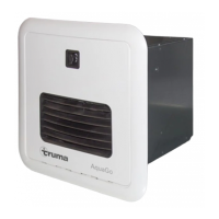
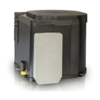
Truma AquaGo® instant water heater (appliance)
Fig. 1 (Unit Casing/Frame partially omitted)
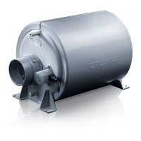
Fig. 2 (rear view of appliance)