23
Assembly
Selecting a location
Install control panels in a location that is protected from moist-
ure and humidity.
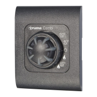
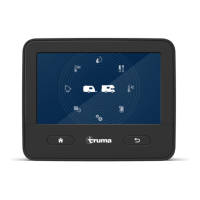
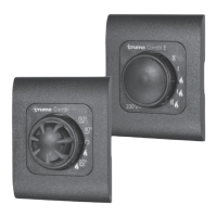
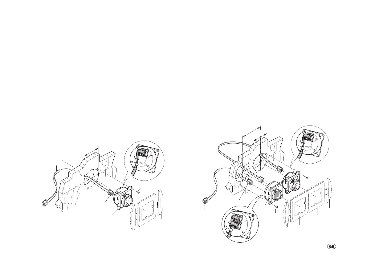
CP classic control panel
– Drill hole with a diameter of 55 mm.
– Attention: Maximum control panel cable length 10 m.
– Attach plug (3) of the control panel cable (2) to the
control panel (1).
– Clamp the control panel cable (2) into the cable duct of the
control panel.
– Route the control panel cable (2) to the heater and plug it in.
– Make sure that all plugs are engaged.
– Secure the control panel with 4 screws (4).
– Fit cover frame (10) with side parts (11).
2
1
4
60
°
40
°
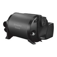
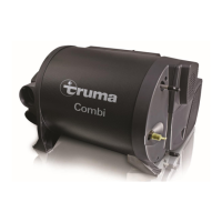
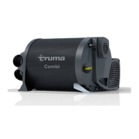
Combi
3
1
4
5
2
10
3
3
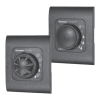
CP classic control panel and
CP E classic power selector switch
(Combi Diesel E only)
– Drill a hole with a diameter of 55 mm for each control panel
(distance between hole centres 66 mm).
– Connect control panel (1) and power selector switch (5)
using control panel connecting cable (6).
– Attention: Maximum control panel cable length 10 m.
– Attach the plug (3) of the control panel cable (2) to the
power selector switch (5). Clamp cables (2 + 6) into control
panel cable ducts.
– Route the control panel cable (2) to the heater and plug it in.
– Make sure that all plugs are engaged.
– Secure each control panel with 4 screws (4).
– Fit cover frames (10) with side parts (11).
66 mm
Ø 55 mm
2
4
4
3
11
11
10
10
6
1
5
3