Foot lever MARS 2.01/2.02
Service Manual MARS 2 1 435 274 - 09/07 147
7.15 Foot lever MARS 2.01/2.02
1. Prepare the operating table (section 2.3 “Operating table” page 11).
2. Disconnect the power supply cable from the mains supply.
3. Switch off the operating table (remote control).
4.
Turn the operating table on the side with a membrane keyboard and lay down safely
on an even surface.
5. Set the foot lever TRAVEL MODE in the directional travel position (see FOOT LEVER
OPERATION pictogram!).
6. Remove the cap on the head side of the running gear and store safely.
7. Take note of where the Bowden cables have been laid!
Unscrew both wheels [10] (4 machine screws [6] in each case).
8. Unscrew both axle holders [1] (2 machine screws [2] in each case) and store safely.
9. Take note of the mounting position of the directional travel Bowden cable!
Unscrew the counternut [9] and adjusting nut [8] on the head end (drive axle) and store
safely.
10. Pull out the directional travel Bowden cable [4] from the locking piece [11] on the foot
lever [5].
CAUTION
Risk of injury from the capacitor voltage.
All LEDs on the membrane keyboard must be out.
CAUTION
Risk of injuries!
Turn the operating table with at least 2 people!
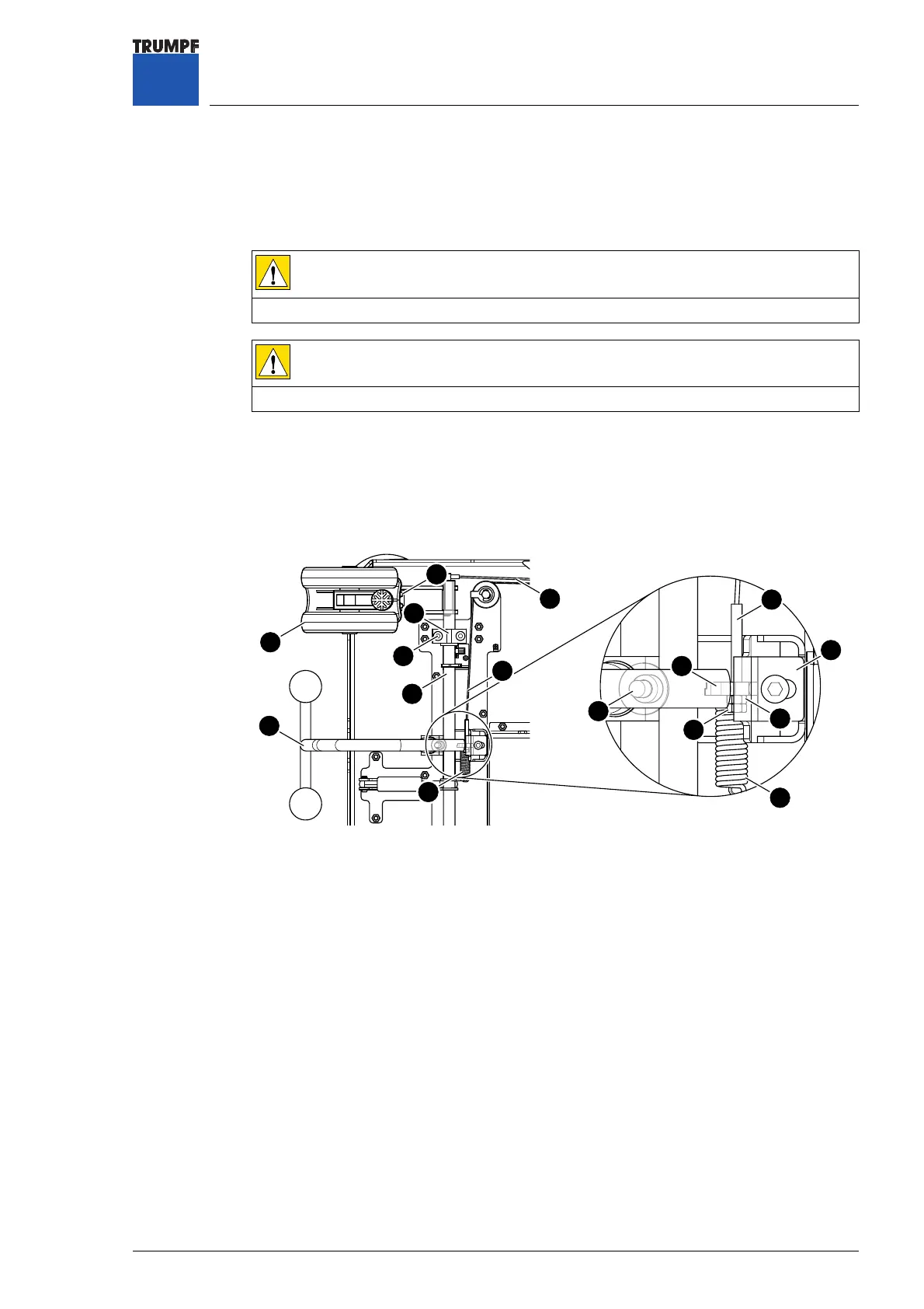
Figure 87 Foot lever MARS 2.01/2.02
1 Axle holder (shaft holder) 8 Setting nut
2 M8x20 machine screw 9 Locknut
3 Brake Bowden cable 10 Rear castor
4 Directional travel Bowden cable 11 Locking piece
5 Foot lever 12 Drive axle (shaft)
6 M8x20 machine screw 13 M8x12 machine screw
7 Tension spring 14 Rest cam
6
4
5
1
2
4
7
9
11
7
3
10
8
12
13
14
 Loading...