Leg section joint (LS)
Service Manual MARS 2 1 435 274 - 09/07 69
5.5 Leg section joint (LS)
1. Prepare the operating table (see section 2.3 “Operating table” page 11).
2. Raise the column to its highest position.
3. Disconnect the power supply cable from the mains supply.
4. Switch off the operating table (remote control).
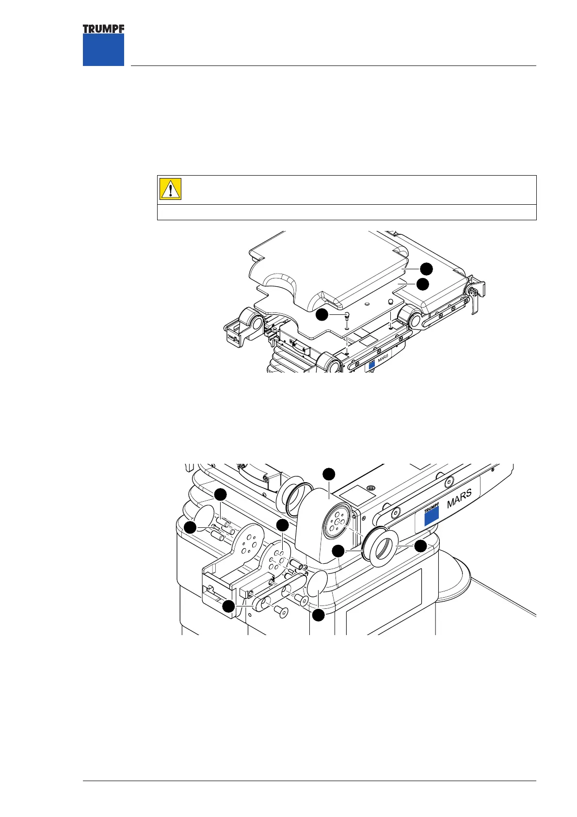
5. Pull pad [1] off the seat section, and put it down in a safe place.
6. Unscrew the plastic plate [2] from the seat section (4 ball-heads [3]), and put them
down in a safe place.
7. Unscrew the standard rail joint [11] (2 countersunk screws), and put them down in a
safe place.
8. Remove the self-adhesive covering foils [4] from the left and right of the LS joint [5].
CAUTION
Risk of injury from the capacitor voltage.
All LEDs on the membrane keyboard must be out.
Figure 35 Pad plate
1 Pad 3 M8 ball-head
2 Plastic plate
3
1
2
Figure 36 Leg section joint
4 Cover foil 8 Slip ring
5 LS joint 9 Groove ring
6 Cylindrical pin Ø 10 mm x 24 mm 10 LS gear
7 M4x12 machine screw 11 Standard rail joint
10
11
8
4
5
6
7
9


 To Next Page