Home
Trumpf
Industrial Equipment
TRUPUNCH 5000
Trumpf TRUPUNCH 5000 User Manual
5
of 1
of 1 rating
536 pages
Give review
Manual
Specs
To Next Page
To Next Page
To Previous Page
To Previous Page
Loading...
5-62
6BMechanical elements
B380EN05.DOC
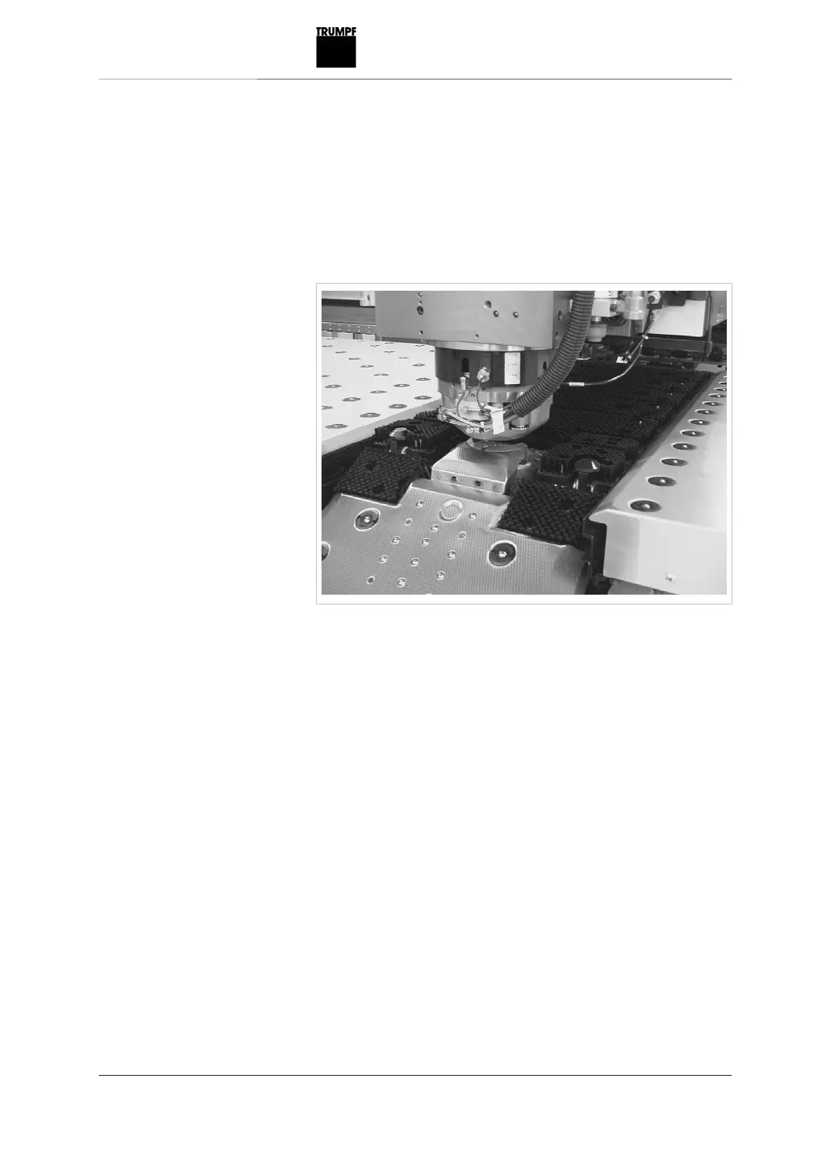
Brush field segment tables, parts flap and
brush tables (optional)
(see section
6.1, p. 5-
50)
Mainten
ance interval: In case of great contamination.
Clean the brush field
segment tables, parts flap
and brush tables
Fig. 26815
415
417
Table of Contents
Table of Contents
6
For Your Safety
23
Terminology
24
Operational Safety
25
Intended Use of the System
25
Measures to be Taken by the User/Operator
27
Danger Signs and Warnings
27
Symbols
27
Signaling Words
28
Information on the Source and Type and How to Avoid the Danger
28
Instructing Personnel
29
Duty of Care When Handling the System
29
Eliminating Malfunctions During Operation
32
Using Designated Spare Parts and Operating Materials
32
Water Protection
33
Measures Taken by the Manufacturer
34
Securing of the Danger Zone of the System
34
Laser Safety
36
Danger Due to Magnetic Fields
37
Overview of Residual Risks
38
Trupunch 5000 Installation Conditions
43
Responsibilities
45
Planning Aid
46
Installation Site
48
Space Requirements
48
Floor Requirements
48
Load Indications
50
Ambient Conditions
53
Air Purity
53
Electrical Supply
54
Power Supply
54
Isolating Transformer
55
Connected Loads/Fuse Protection
57
Remote Diagnostics
57
Network Connection
58
Compressed Air Supply
59
Operating Materials
62
Operating Materials for the Hydraulic System
62
Cooling Water for the Cooling Unit
63
Materials
63
Pallets for Sheetmaster (Optional)
65
Older Tool Cartridges
65
New Multitools and Tapping Tools
67
Transport
68
Measures to be Taken by the Customer
69
Machine Delivery
69
Unloading the Machine from the Truck
70
Transporting the Machine to the Installation Site
73
Installing the Machine
74
The Machine Concept
78
Technical Data
81
The most Important Assemblies
82
Machine Frame
83
Punching Head
84
Coordinate Guide with Linear Magazine
85
Drives
86
Part Removal
87
Tools
88
The Tool System
88
Components of a Tool Set
90
Punch
90
Punch Selection
92
Alignment Ring
94
Die
94
Stripper
96
Stripper Selection
97
Continuation of Table 2
102
Stripper Selection Examples
104
Tool Innovations
107
Roller Tools
107
Roller Deburring Tool and Deburring Multitool
109
TRUMPF Multitools
110
Tapping Tools
115
Clean Cutting with TRUMPF Multishear
117
Press Brake Bending with the TRUMPF Multibend
118
Quick Beading
119
Engraving
119
Adaptive Stroke Calibration
120
Maximum Output Tables
122
Calculation Formulae
122
Influencing Factors
123
Punch
125
Dies
125
Stroke Rate Tables
130
Influencing Factors
130
Standard Tool
131
Whisper Tool
133
Standard Tool with Active Presser Foot
134
Long Standard Tool with Active Presser Foot
135
Multitool
136
Forming Tool
137
Standard Tool
138
Whisper Tool
140
Standard Tool with Active Presser Foot
141
Long Standard Tool with Active Presser Foot
142
Multitool
143
Forming Tool
144
Technical Information: Automation
145
Automation Made to Measure
145
Overview of Automation
146
Simple Automation
147
Sheetmaster
148
Loading Table (Trupunch 5000 Only)
152
Gripmaster
153
Shearmaster (Not Trupunch 3000)
155
Flexible Manufacturing Cell
157
Toolmaster (Only Trupunch 3000 and Trumatic 6000)
158
Cart Systems with Travel Rails
161
Cart System with Toothed Belt Drive
163
Characteristic Features
164
Sortmaster Box
165
Sortmaster Pallet
166
Flexible Manufacturing Cell with TRUMPF Compact Store
168
Flexible Sheet Machining System
170
Control System and Administration for Connection to Storage
171
Control System Technology
172
Programming
174
Directly at the Machine
174
In the Office
175
Defining Machining: What Is Done Automatically
176
The most Important Options
177
10.1 Active die
178
10.2 die Spray Lubrication
179
Brush Tables with Loading and Unloading Aid
180
10.4 Height-Adjustable Clamps
181
Operation
183
Part 1: Control Elements
189
Control Elements: Overview
189
Control Panel with Color Display
191
Operating Elements of the Machine
192
Operating Elements of the Control System
196
Keyboard
200
USB Connection
201
Part 2: User Interface
202
Structure of the User Interface
202
Menu Bar
203
Status Line
203
Message Bar
204
Softkey Bar
204
Display Area
204
Machine Submodes
205
AUTOMATIC Submode
205
MDA Submode
206
JOG Submode
206
Control Areas
207
Diagnostics
208
PRODUCTION Operation
209
PRODUCTION Single Job
209
Layout of Graphics
209
PRODUCTION Production Plan
212
NC Program Management in the NCU
214
PRODUCING Machine Components
215
PRODUCTION Program Options
216
PRODUCTION Switch Elements
217
Operating the Switch Elements
217
General Switch Elements
218
Z Axis Calibration (Optional)
220
Switch Elements H+L Diagnostics
221
Sortmaster Box Switch Elements (Optional)
222
Gripmaster Switch Elements (Optional)
222
Sheetmaster Axis Switch Elements (Optional)
222
Sheetmaster General Switch Elements (Optional)
223
PRODUCTION: Tables
224
Loading Sheets
225
Sheet Unloading
228
Sheet Technology
236
Workpiece Removal
237
Repositioning
242
Tool Technology - Tapping (Optional)
243
Tool Technology - Engraving (Optional)
244
Tool Technology - Tapping (Optional)
245
Tool Technology - Punching/General
246
Tool Technology - Quick Beading (Optional)
249
Tool Technology - Multishear (Optional)
249
Tool Technology - Roller Tool (Optional)
251
Tool Technology - Engraving (Optional)
253
SETUP Operation
254
SET-UP Switch Elements
254
General Switch Elements
254
Punching Switch Elements
255
Switch Elements H+L Diagnostics
255
Switch Elements H+L Diagnostics
256
Sortmaster Box Switch Elements (Optional)
256
Gripmaster Switch Elements (Optional)
257
Support Table Switch Elements (Optional)
257
Sheetmaster Switch Elements (Optional)
258
Stripper Unit Switch Elements (Optional)
259
Toolmaster Switch Element (Optional)
259
Loading Table Switch Elements (Optional)
260
SET up Jog Mode
261
Mda Set-Up
262
PROGRAMMING Operation
263
NC Editor
263
PROGRAMMING NC Program Management
263
PROGRAMMING File Management
265
Sending NC Programs from the Program Manager
268
TOOLING Operation
269
TOOLING Tool Table (Autom.)
269
TOOLING Tool Table (Manual)
269
Setting up Rails
269
Setting up the Toolmaster (Optional)
269
Set up Rail/Tool (Optional)
271
Selecting NC Programs
272
TOOLING Rail Allocation
273
TOOLING Tool Allocation
273
TOOLING Tools
275
Required Tools
275
Tool Change List
275
General Tool Data
276
Tool Master Data/Status Data
277
Explanation of the Tool Data
279
MAINTENANCE/START-UP Operation
284
Maintenance/Start-Up Data Backup
284
Changing the Configuration for a Partial Backup
286
Starting a Partial Backup Manually
286
DIAGNOSTICS Operation
288
10.1 DIAGNOSTICS Fault Diagnostics
288
10.2 DIAGNOSTICS I/O Diagnostics
289
10.3 DIAGNOSTICS Remote Diagnostics
289
DIAGNOSTICS Display Original Position
290
Integrated MDR Operation (Optional)
291
11.1 MDR Message Text
291
MDR Creating and Modifying Message Texts
292
MDR Displaying and Editing Machine Data
294
MDR Creating and Changing Interruptions
296
11.5 MDR Evaluating Machine Data
297
11.6 MDR Displaying the Times in List Form
298
11.7 MDR Changing the Time
298
Part 3: Operating the Machine
299
Switching the Machine on and off
300
Switching on the Machine
300
Switching off the Machine in the Event of Malfunctions or Emergencies
301
Switching off the Machine
301
Executing a Program
302
Executing a Program Automatically
302
Executing a Program with the Softpunch (Optional)
303
Triggering a Single Stroke
304
Changing the Forming Depth
305
Program Stop During Execution
306
Stopping Programs
306
Reentry into a Program
307
Working with the Production Plan
309
Creating a Production Plan
309
Executing a Production Plan
310
Restarting the Execution of the Production Plan after a Program Interruption
311
Moving the Axes Manually
312
Releasing the Drive Brakes
313
Releasing the X and y Axis Drive Brakes
313
Manual Execution of the Lubrication Cycle
314
Diagnostic Functions
315
Fault Diagnostics
315
Displaying Machine Inputs and Outputs
316
Remote Diagnosis Via Pcanywhere
317
Querying the Software Version
318
Managing Master Files
318
Uploading NC Programs from the USB Interface
318
Uploading NC Programs from the Hard Disk
319
Output of NC Programs Via USB Ainterface
320
NC Program Output on the Hard Disk Drive
321
Program Part Output Via USB Interface
322
Deleting NC Programs from the Program Manager
323
NC Program Management
324
Displaying NC Text
324
Editing NC Text
325
Searching for a Block in the NC Text
325
Searching for a Function in the NC Text
326
Searching for and Replacing a Function in the NC Text
326
Inserting an Additional Line
328
Copying and Inserting Text Passages
329
Deleting Text Passages
330
Editing Tables Based on NC Text
330
Tooling
332
Creating an Automatic Tool Table and Loading the Tool Rail
332
11.2 Manually Loading/Unloading Tools
333
Loading a Tool from the Rail Onto the Toolmaster (Optional)
334
11.3 Correcting Clamp Positions
335
11.4 Removing an Active Tool
336
11.5 Unloading All Tools
336
Operating the Integrated MDR
336
12.1 Creating a Message Text
337
12.2 Assigning a Message Text
337
12.3 Splitting up an Interruption Period
338
12.4 Evaluating Machine Data
339
Adjusting the Pressure Foot Pressure
340
If Problems Arise
341
Removing Stripper from Stripper Adapter
341
Removing the Punch from the Punching Head
343
14.3 Removing the die from the die Holder
346
14.4 Replacing the Stripper Segment
347
Using Shearmaster (Optional)
348
Starting and Stopping Shearmaster Manually
348
15.2 Change Scrap Container
349
15.3 Use Shearmaster in Stacking Mode
349
15.4 Technical Notes
350
15.5 Correcting Malfunctions
350
Release Tilted Scrap Skeleton
350
Release Tilted Scrap from the Chute
351
Using Height-Adjustable Clamps
352
16.1 Moving Height-Adjustable Clamps
352
16.2 Utilizing Height-Adjustable Clamps
353
16.3 Help if Problem Arises
353
General Guidelines
358
Maintenance Overview
359
Lubrication
362
Overview
362
Maintenance Instructions
365
Longitudinal and Transverse Guides
365
Transverse Carrier and Table Support Bearings
367
Central Lubrication
368
Hydraulics
369
Zero Stop Sensor (Only Trupunch 5000 with Automation)
374
Punch Spray Lubrication
375
Die Spray Lubrication (Optional)
378
Tapping Lubrication Unit (Optional)
380
Die Clamping Piston Clamp
384
Rail Transverse Carrier and Table Support
385
Punch Holder
386
Active die (Optional)
386
Hydraulic System
388
Overview
388
Depressurizing the Accumulator System
389
Maintenance Instructions
391
Hydraulic Accumulator
391
Hydraulics Hose Lines
395
Hydraulic Unit
397
Pneumatic System
400
Overview
400
Maintenance Instructions
401
Air Cushions (Optional)
401
Punch Spray Lubrication
402
Mechanical Elements
404
Overview
404
Maintenance Instructions
405
Punching Tool Adapter
405
Chip Vacuum System: Side Channel Blower
406
Chip Vacuum System: Vacuum Pipe
408
Chip Vacuum System: Chip Flap
409
Chip Vacuum System, Complete
411
Tool Cartridge Support Slat
413
Clamps
414
Racks and Guide Rails
415
Index Pin(S)
415
Brush Field Segment Tables, Parts Flap and Brush Tables (Optional)
416
Brush Field Segment Tables
418
Compressed Air Maintenance Unit
421
Control Panel
422
Electrics
423
Overview
423
Maintenance Instructions
424
Switch Cabinet: Connectors and Clamping Screw Connections
424
Switch Cabinet: External Air Circuit
424
Switch Cabinet: NCU Battery
425
Buffer Battery Box PC
427
Safety Light Barrier and Light Barrier Parts Flap (Optional)
430
Inductive Proximity Switch
431
Sensor System - Stripper Sensor
432
Cooling Unit
436
Maintenance Instructions
436
Procedure after a Collision
441
Handling the Setting Device
442
Assigning the Punch and Alignment Ring
442
10.2 Determining the Tool Length
444
Regrinding Tools
445
11.1 Compensating the Regrind Amount
446
General Guidelines
455
Maintenance Overview
456
Sheetmaster and Gripmaster Maintenance Overview
456
Sheetmaster and Gripmaster Maintenance
456
Sortmaster Box Maintenance Overview
457
Overview
457
Maintenance Overview for Double Cart with Toothed Belt Drive
459
Shearmaster Maintenance Overview
459
Lubrication
461
Lubrication Chart for Sheetmaster with Gripmaster
461
Lubricant
462
Maintenance Instructions
463
Axis Guide Strip at the Sheetmaster
463
Pick-Up Columns of the Carrier Cups at the Sheetmaster
464
Stripper Unit (Optional) Guide Rod on the Sheetmaster
465
Safety Device of the Suction Frame at the Sheetmaster
466
Guide Rods of the Sheet Thickness Gauge at the Sheetmaster
467
Central Lubrication on the Sheetmaster
468
Axis Feedgear at the Sheetmaster
469
Z Axis Feedgear at the Sheetmaster
469
Y Axis Feedgear at the Sheetmaster (Optional)
469
Guide Rails at the Gripmaster
470
Stop Pins on the Movable Gripmaster
470
Grippers on the Gripmaster
471
Lubrication Chart for Toolmaster (40/70)
472
Maintenance Instructions
474
Lifting Device Bearing
474
Indexing
475
Shifting Unit (Toolmaster (70))
476
Rotary Table
477
Central Lubrication
477
Drive Motor Gearbox
478
Lubrication Chart for Sortmaster Box
479
Lubricant
480
Maintenance Instructions
480
Rolling Elements of the Four-Point Bearing
480
Inner Toothing of Slewing Ring
482
3.10 Lubrication Chart for Sortmaster Pallet
483
3.11 Lubricant
484
3.12 Maintenance Instructions
484
Cam
484
Flange Bearing Unit
485
Roller Chains and Chain Wheels
485
Flat Gearbox
485
Screw Joints
486
Weld Joints
486
Lubrication Chart for Double Unloading Cart
487
3.14 Lubricant
488
3.15 Maintenance Instructions
488
Track Rollers
488
Ball Bearings
489
Flange Bearing Unit
489
Roller Chains and Chain Wheels
490
Flat Gearbox
490
Screw Joints
491
Weld Joints
491
Lubrication Chart for Double Cart with Toothed Belt Drive
493
3.17 Lubricant
494
Running Surfaces
494
Ball Bearings
495
Flange Bearing Unit
496
Roller Chains and Chain Wheels
496
Flat Gearbox
497
Screw Joints
497
Weld Joints
498
3.18 Lubrication Chart for Shearmaster
499
3.19 Lubricant
499
3.20 Maintenance Instructions
500
Pneumatic Components
507
Pneumatic Components on the Sheetmaster and Scissor Table
507
Overview
507
Maintenance Instructions
508
Pressure Regulator
508
Vacuum Hoses in the Suction Frame
510
Filters in the Suction Cup Vacuum Connections
511
Pneumatic Bellows Cylinder at the Scissor Table
512
Pneumatic Hoses at the Scissor Table
512
Mechanical Components
513
Mechanical Components at the Sheetmaster and Gripmaster
513
Overview
513
Maintenance Instructions
514
Dowelling of Sheetmaster, Gripmaster and Support Table with Movable Gripmaster
514
Vacuum Cups on the Sheetmaster
515
Axis, Z Axis, and y Axis (Optional) Cable Tow Chains at the Sheetmaster
518
Mechanical Components on the Shearmaster
519
Scrap Container
519
Conveyor Belt
520
Electrical Components
521
Maintenance of the Electrical Components at the Sheetmaster and Scissor Table
521
Maintenance Instructions
521
Switch Cabinet of the Sheetmaster: TASC
521
Control System Battery
521
Light Barriers at the Scissor Table
522
Test Certificate
523
Measurement Result
525
Reference Workpiece
526
Position of the Measuring Points
527
5
Based on 1 rating
Ask a question
Give review
Questions and Answers:
Need help?
Do you have a question about the Trumpf TRUPUNCH 5000 and is the answer not in the manual?
Ask a question
Trumpf TRUPUNCH 5000 Specifications
General
Brand
Trumpf
Model
TRUPUNCH 5000
Category
Industrial Equipment
Language
English
Related product manuals
Trumpf TruHeat HF 5000 Series
164 pages
Trumpf TruPlasma RF 1003
360 pages
Trumpf TruHeat HF 1000 Series
164 pages
Trumpf TC 2020R
101 pages
Trumpf BendMaster 150
258 pages
Trumpf BendMaster 60
258 pages
Trumpf PFO 33
176 pages