4
Chapter 2 - Measurements Available
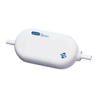
Flow Rate Measurement
Flow rate data can be obtained through the linearized analog output
or via the serial interfaces.
Flow rate can be output in units of standard liters per minute (Std
L/min*) or in volumetric units of liters per minute (L/min). Refer to
Appendix C
for a description of the two measurements. Selecting
between the two measurements is accomplished through the serial
interfaces. Refer to the Command Set
section for instructions.
*TSI instruments define standard conditions as 21.1°C (70° F) and
101.3 kPa (14.7 psia, 1 bar).
Temperature Measurement
These flowmeters have an independent sensor in the flow tube to
measure the gas temperature. The information is used for internal
temperature compensation of the flow sensor element and for
converting flow from standard to volumetric units. This flow