31
Chapter 5. Changing Flow Hoods
This chapter identifies the flow hood parts and gives instructions for assembling the flow hood.
Flow Hood Parts Identification
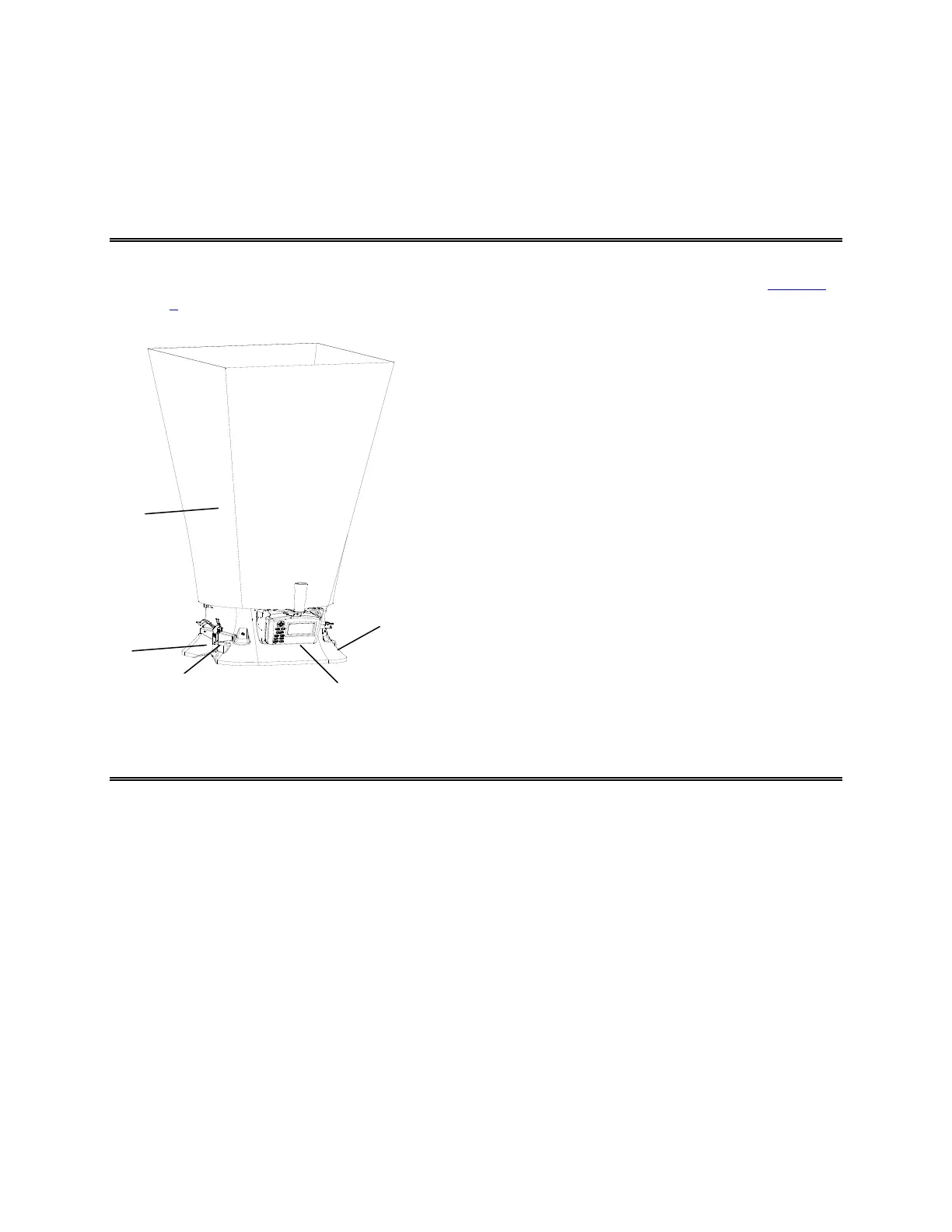
Figure 13 identifies the major parts of the capture hood, which are described in the following paragraphs.
Before using the hood, please familiarize yourself with the various parts. You may also refer to Tables 1
through 3
.
1 Fabric hood - Basic hood assembly
2 Base allows micromanometer to be attached
3 Micromanometer with display
4 Flap Actuator
5 Read Switch
Figure 13: Flow Hood Components
Hood Assembly
The Flow Hood is shipped from the factory partially assembled with the 2 ft × 2 ft (610 mm × 610 mm)
nylon hood attached to the base. If you wish to use another hood size, see “Changing Hoods,” below.
To complete the assembly of the 2 ft × 2 ft (610 mm × 610 mm) hood, follow these six steps:
1. Place the base of the capture hood
on the floor.
2. Lift the top of the fabric. Insert one end of a support pole into its pole mount in the base. There is a
cup in each corner of the frame to accept the other end of each support pole.
3. Grasp the support pole. Bend the pole slightly to insert the top end of the pole into the support pole
cup located in the opposite corner of the fabric frame. The poles are connected to the frame corners in
a crisscross fashion as shown in Figure 14.
2
3
4
1
5