TM2
The TallyMan controller should be installed in a standard 19” rack with good ventilation, no other
special precautions need be taken, further information regarding earthing, mounting, power etc may
be found in the Safety section.
Connections
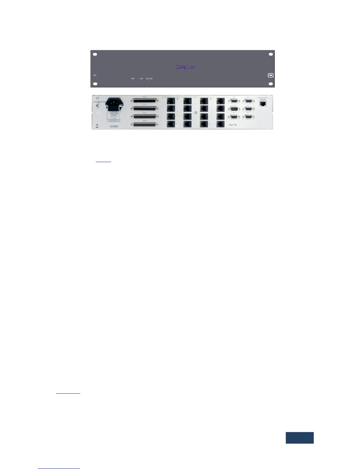
Tally 1 This is for the parallel tallies. 1 – 32
Tally 2 This is for the parallel tallies 33-64
Tally 3 This is for the parallel tallies 65-96
Tally 4 This is for the parallel tallies 97-128
Control 1 RS422 – User Assignable. Used for Mixer/Router/Multiviewer connection
Control 2 RS422 – User Assignable. Used for Mixer/Router/Multiviewer connection
Control 3 RS232 – User Assignable. Used for Serial configuration of Controller Network settings
and available for Mixer/Router/Multiviewer connection
Control 4 RJ45 UMD Display Ports - Power and RS422 serial data is available from these ports.
Control 5 RS422 – User Assignable. Used for Mixer/Router/Multiviewer connection
Control 6 RS422 – User Assignable. Used for Mixer/Router/Multiviewer connection
Control 7 RS422 – User Assignable. Used for Mixer/Router/Multiviewer connection
Ethernet This is for configuration via the configuration PC and network comms with IP capable
devices.
Power The unit is powered via an IEC 60320 C14 coupler. The inlet is auto ranging 100-
240V. No cable is supplied with this device.
Back to Top ^
 Loading...