20
3.2 FG-DCTL – “Cut-to-Length” Addressable Box:
The FG-DCTL “Cut-to-Length” addressable box allows the connection of custom lengths (from 1 to 45
meters) of FG-ECS, FG-ACS, FG-ECX and FG-ACX sense cable to the main bus wire; this box is
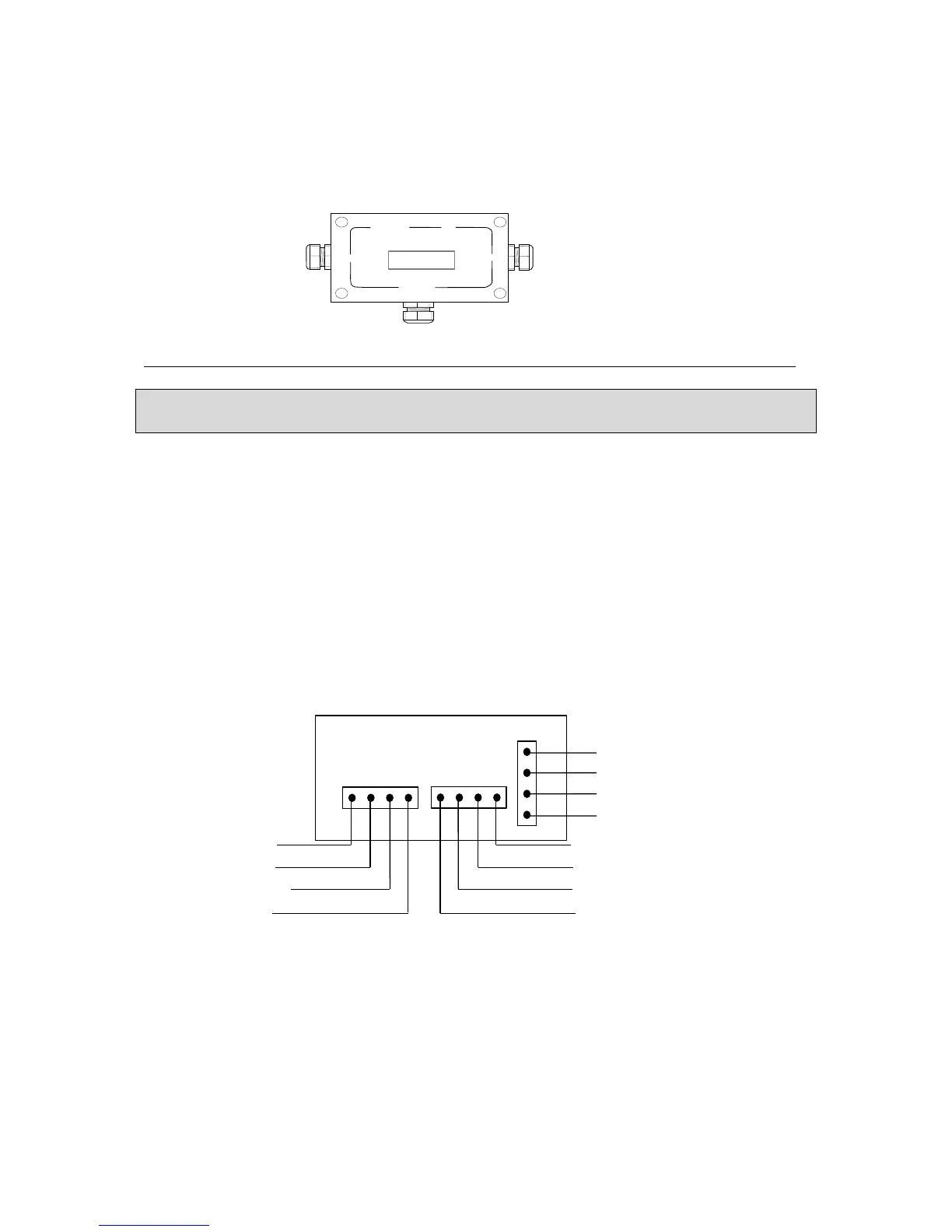
provided with three holes with cable glands: 'INPUT', 'OUTPUT' and 'SENSOR '.
INPUT OUTPUT
SENSOR
The connection diagram is located on the addressable box packaging. (See below for details)
Caution:
In the last FG-DCTL addressable box, the circuit must be completed with a shunt in the OUTPUT of
the circuit board (between A and B).
The INPUT is linked to the Belden cable coming from the FG-SYS Digital Unit, or from the
previous FG-DCTL addressable box
The OUTPUT is linked to the Belden cable leaving towards the next FG-DCTL addressable box
The SENSOR output is linked to the FG-ECS, FG-ACS, FG-ECX or FG-ACX sense cable.
Up to 30 FG-DCTL boxes can be installed on one circuit, with a maximum of 70 FG-DCTL boxes on
one panel.