21
3.3 FG-DTC, TTK Bus Diversion
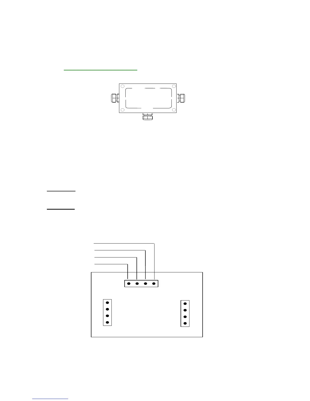
The TTK Bus Diversion box makes it possible to break up a detection circuit into two parts. The box is
provided with three cable glands: ‘INPUT’, ‘OUTPUT2’ and ‘‘OUTPUT1’.
FG-DTC Diversion Box Diagram:
INPUT OUTPUT2
OUTPUT1
The connection diagram is located on the box packaging.
See below for instructions on how to connect the FG-EC or FG-AC cables to the main bus wire, or to
connect the sense cables to each other.
The INPUT is linked to the Belden cable coming from the FG-SYS Digital Unit, or from the last
FGDTCS diversion box
OUTPUT1 is linked to the FG-EC or FG-AC sense cables.
OUTPUT2 corresponds to the Belden cable at the end of the circuit.
CAUTION: When an output is not being used (for example OUTPUT 2 in the last
diversion box), a shunt is needed between A and B.
CAUTION: Installation of the FG-DTC Diversion box must be done when the FG-SYS
Digital Unit is switched off.


 To Next Page