6
2. ELECTRICAL CHARACTERISTICS
- Power Supply: 100-240 VAC - 0.35-0.2A - 50/60 Hz
- Max. Consumption : 15W
- Power Thermal Fuse 2x0.5 A on the secondary
- Rating : Class 2 not Inherent Limited
It is recommended electrically to protect the digital unit with a circuit breaker from 0.5 A.
Nine Dry Relays Characteristics:
Type : 1 RT Mechanical Signal Relay
Max. switching voltage. : 125 VAC / 60 VDC
Max. switching Intensity : 1 A
Max. switching capacity : 62,5 VA / 30 W
Working load min.: 5 VDC - 1 mA
Nominal load : 0,5 A à 125 VAC
1 A à 24 VDC
Sensing Cables:
- Rating : 12 VDC
- Nominal Voltage on the sense cable circuit (all voltages referred to Ground):
- 1A, 2A, 3A, 1B, 2B, 3B: 5 VDC
- 1D, 2D, 3D: 12.3 VDC
- 1C, 2C, 3C: 0 VDC (electrically connected to Ground)
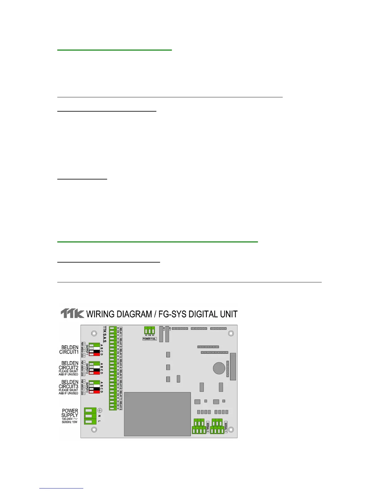
3. ELECTRICAL CONNECTION OF THE FG-SYS DIGITAL UNIT
Connections are done on the electronic board of the digital unit. The connector blocks are directly
accessible and removable (male parts) on the FG-SYSF and E; for the FG-SYS F (metal enclosure
wall mounted version), it is necessary to turn the key button of the front face to open it.
See Appendix n°1: “FG-SYS E or F Digital Unit Connection” page 57, and also available separately
inside the unit.
3.1 Connection of the FG-SYS Digital Unit to the Earth