19
3. ACCESSORIES INSTALLATION
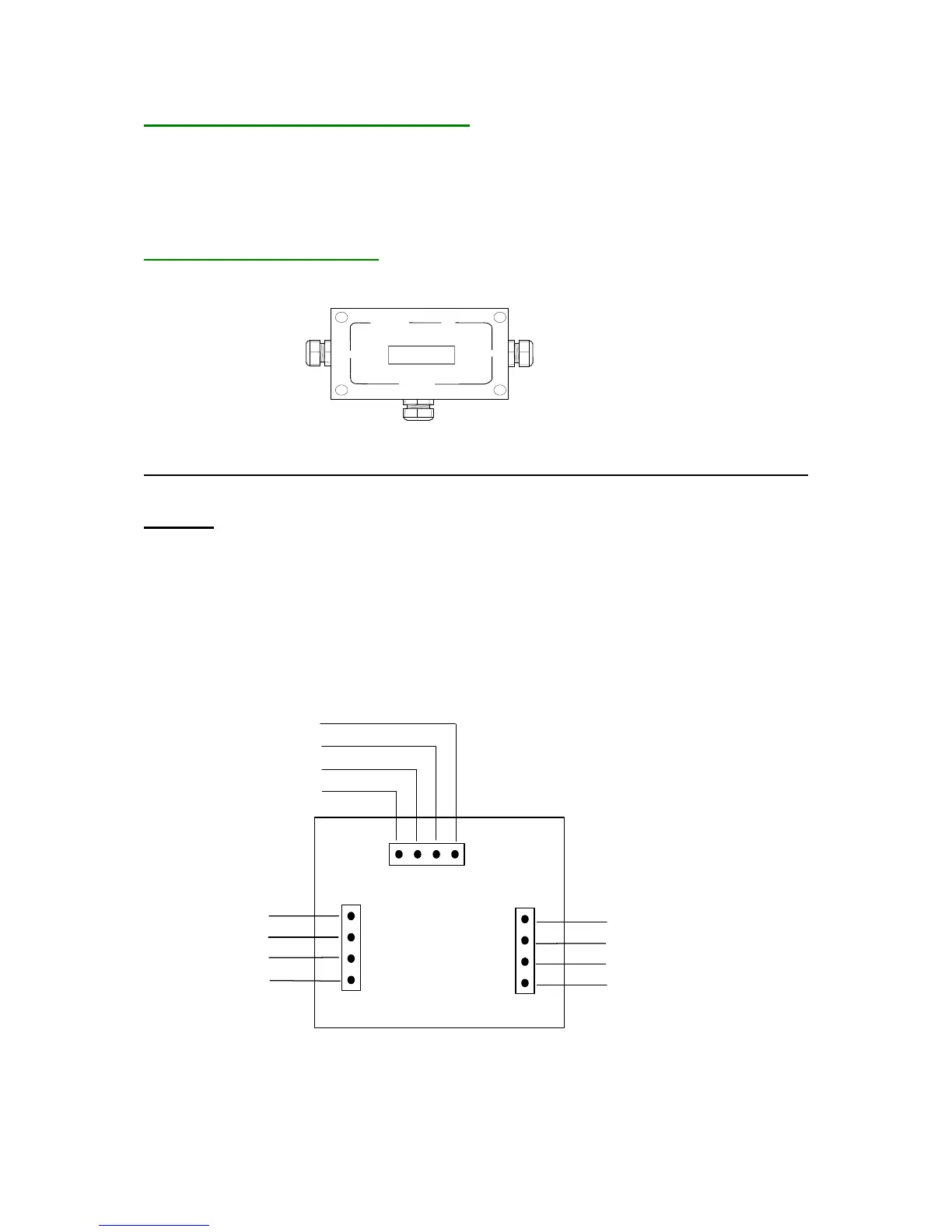
3.1. FG-DTCS Addressable Box:
The FG-DTCS diversion box allows connection of the FG-ECS sense cable on the main bus wire; this
box is provided with three holes with grommets: ' INPUT', ' OUTPUT' and ' FG-ECS '.
FG-DTCS Diversion Box Diagram:
INPUT OUTPUT
FG-ECS Sector Sense Cable
The schema of connection is located on the plastic bag of the sector diversion box. Refer to the
diagram to connect the cables below.
Caution :
In the last Sector Diversion Box, We must end with a shunt in OUTPUT in the circuit
board, between A and B.
Installation of the FG-DTCS Diversion box must be done when the FG-SYS Digital Unit
is switched off.
INPUT corresponds to the Belden cable coming from the FG-SYS Digital Unit
OUTPUT corresponds to the Belden cable leaving towards the following Diversion Box
FG-ECS corresponds to the FG-ECS sense cable.