7
CAUTION:
Respect the rules for Electromagnetic Compliance standards - (E.M.I.):
It is absolutely necessary to connect the back of the front face to the site (building)
earth.
The greenhouse cables and the screw n°3, with the identification "Earth ", are
available for this purpose.
3.2 Connection of the Power Cable
An power cable H07VV-F 3 x 1,5 mm², not provided by TTK, makes the electric connection of the
digital unit. Connect the cable on the male and female connector blocks 3 points, for this use; remove
the female to connect the power cable, and then place it back to the male.
The three terminals: L, N and Earth are indicated on the board.
Use the stuffing box n°3 for the cable.
(See Appendix n°1: FG-SYS E or F Digital Unit Connection)
Caution: Do not switch the FG-SYS Digital Unit On
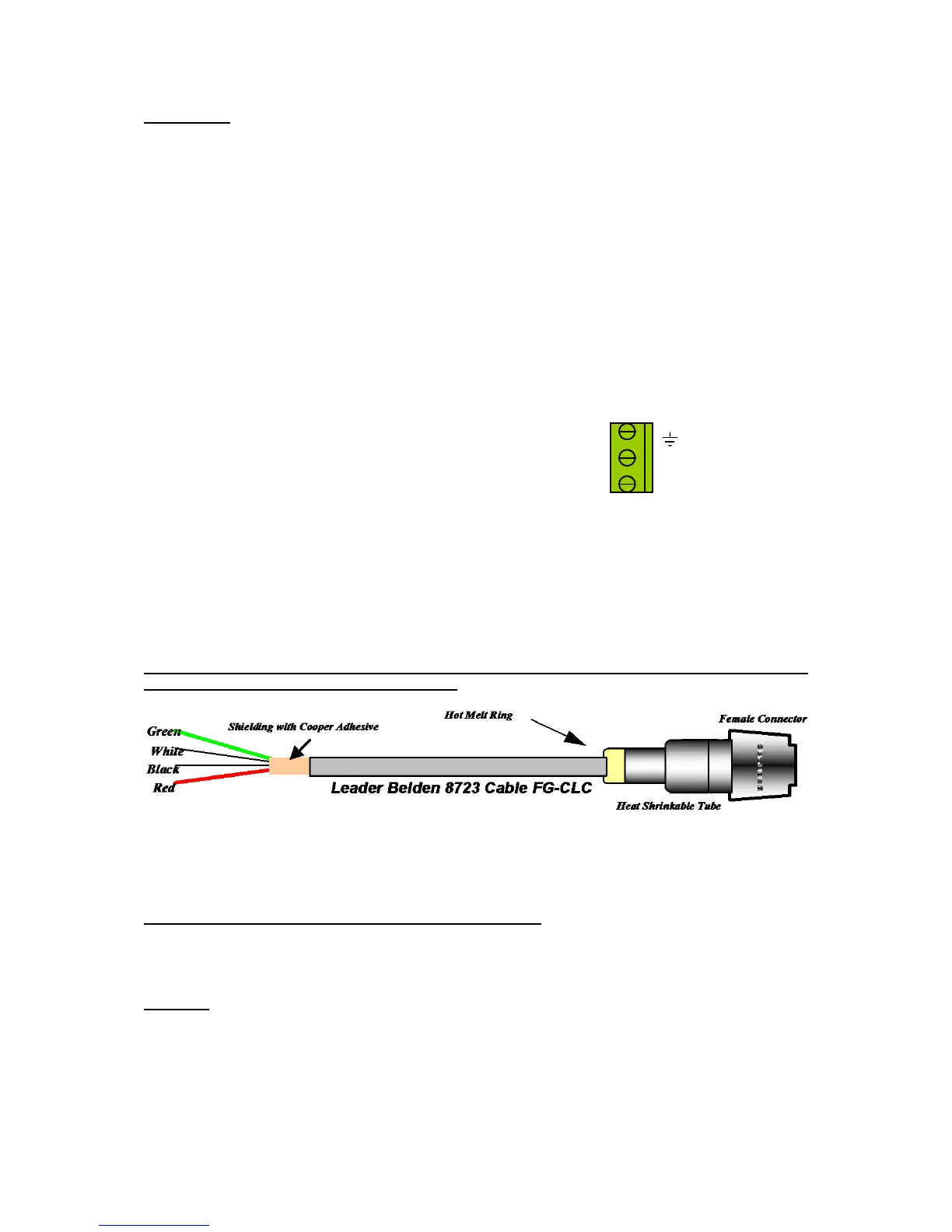
3.3 Connection of the FG-CLC Leader Cable
(See Appendix n°1: FG-SYS E or F Digital Unit Connection page 57, and also available
separately inside the unit)
Each circuit of sense cables is connected to the FG-SYS Digital Unit with a TTK Leader Cable (Belden
8723), ref. FG-CLC
Caution: An inversion between the two couples red + black, and green + white, damages the
electronic of the first connected sense cable.
Three circuits are available; first of all to use circuit n°1, then if necessary, following circuits.
Each circuit has a maximum capacity of 40 sense cables.
When the circuit n°2 is used: Remove the existing shunt between 2A and 2B.
When the circuit n°3 is used: Remove the existing shunt between 3A and 3B.
Caution:
To avoid the electromagnetic disturbances and emissions (ECM), it is necessary to connect the
shielding of the leader cable to the earth. Fix, using a metal cable clamp, the shielding of the
leader cable (available to the back)
(See Appendix n°1: FG-SYS E or F Digital Unit Connection, page 57.)