35
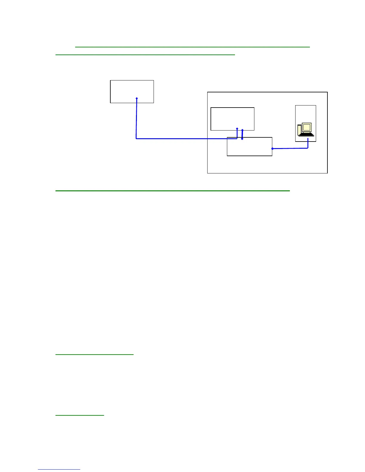
3.3. Physical Representation of a Sample Site with Several FG-SYS
Digital Units Connected to the Same Supervisor, B.M.S.:
(Remark: These systems were not evaluated by UL)
FG-SYS
Bâtiment n° 1
Bâtiment n° 2 FG-SYS
PC
Câble RS485
Convertisseur Série
RS485-RS232
Câble RS232
4. Minimum equipment required for the installation of TOPSurveillance™:
4.1. Pentium III (or equivalent) workstation with mouse, keyboard and available serial port
RS232C
4.2. OS Windows '98, 2000, XP, NT, Vista, Windows 7 (32 or 64 bit) or Windows 8 (32 or 64
bits)
4.3. SVGA graphics card with 4 MB VRAM
4.4. Sound card and speakers
4.5. SVGA display with a 1024x768 resolution
4.6. Memory 252 MB RAM
4.7. 1 GB hard disk minimum
4.8. CD-ROM
For a single FG-SYS detection unit:
4.9. DB9 RS232 serial cable between the FG-SYS and PC
For several FG-SYS detection units or when the distance between the PC and the FG-SYS detection
unit is greater than 100 meters:
4.10. RS232/RS422 or RS485 converter
4.11. DB9/DB25 RS232 serial cable between the converter and the PC
4.12. RS422 or RS485 cable (120 Ohms) between the converter and (or) plant (s) FG-SYS
5. JBUS Communication
The integration on the FG-SYS JBUS/MODBUS protocol Digital Units permits the supervision of the
current status of all connected sense cables. The two types of alarms – leak and cable break – are
coded using different flags and the location is represented in metres.
Following the creation of new features, a new Modbus Table has been created for the FG-SYS;
however former Modbus Table has been retained in parallel for compatibility reasons.
The former Modbus Table can be found in the FG-SYS Digital Unit documentation.
Physical connection
The information provided by the Digital Unit can be exploited in different ways:
- Modbus TCP (Modbus over IP) port 502.