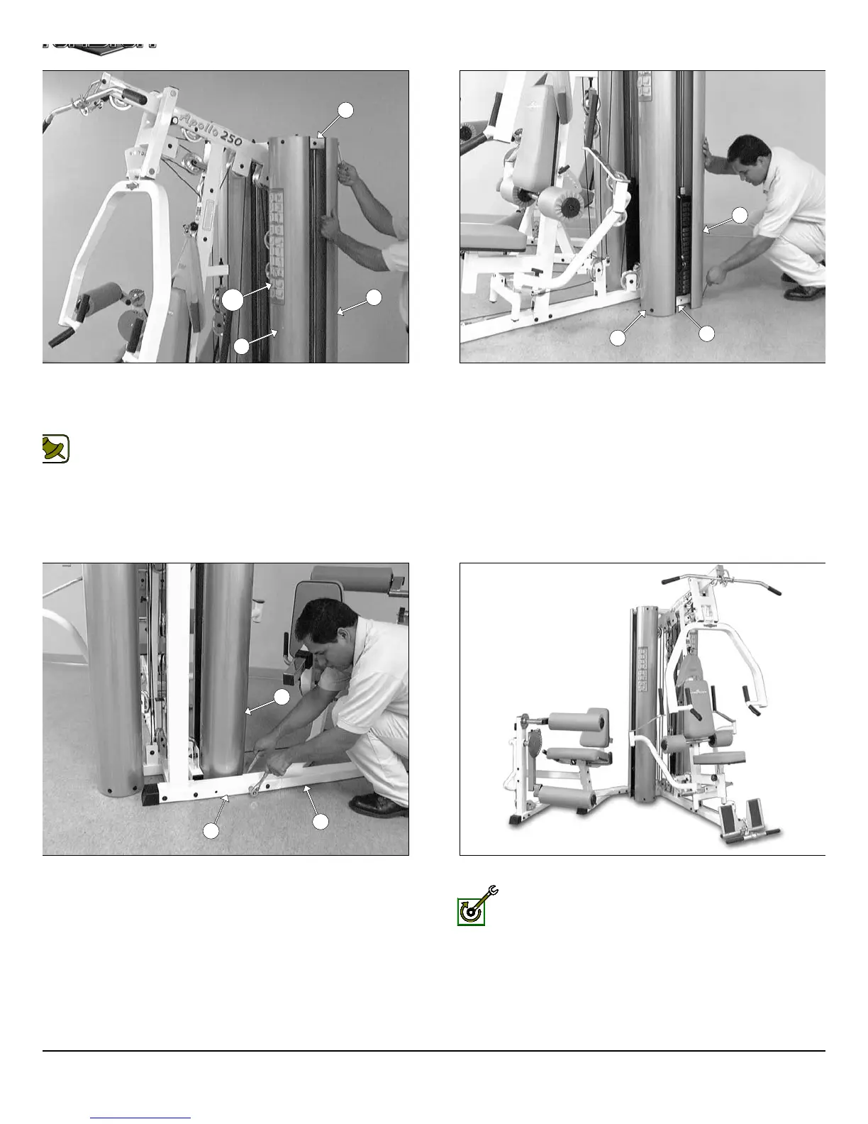
IG. 80 After the cables have been adjusted, proceed to attach the
ur Weight Shrouds (#22) to the two Guide Rod Retainers (#20).
ing eight Hex Head Cap Screws 1/4-20 X 3/4 (#114), and eight Flat
ashers 1/4 (#97).
Note: Refer to Fig. 87 on page 30 for further clarification of this
hardware assembly.
IG. 82 After the Weight Shrouds (#22) have been assembled,
oceed to complete the assembly of the Leg Extension Main Frame
9) and the Rear Upright (#4) using one Hex Head Cap Screw 3/8-16
4 1/4 (#104), two Flat Washers SAE 3/8” (#91) and one Nylon Insert
ck Nut 3/8-16 (#100).
FIG. 81 Next, attach the bottom of the four Weight Shrouds (#2
to the Base Frame (#2) using eight Hex Head Cap Screws 1/4-20 X 3
(#114), and eight Flat Washers 1/4 (#97).
This concludes the assembly of the AP-250S_AP-250D.
Fully Fasten: It is highly recommended that you double check
and fully fasten all hardware assemblies and inspect the cable
routing.
23
22
22
20
128
22
22
2
9
4
22
AP-250S_AP-250D Apollo 2-Stack Gym Syste