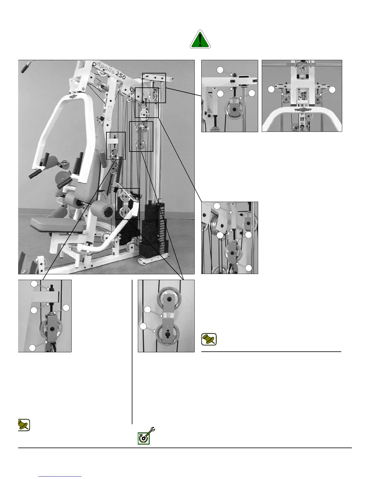
he Diagram below depicts the location of the cable adjustments on each
orkstation. It is imperative that you maintain the cables’ proper adjust-
ent to ensure a safe and smooth operation.
Caution: The cables should be inspected and adjusted period
cally to avoid any slack in the cables which would, consequentl
prevent any damage to the equipment or personal injury.
Cable Adjustment for:
Adjustable Stopper (#33)
1. Loosen the Regular Hex Nut 1/2-13 (#99).
2. Twist the Adjustable Stopper (#33) to left or right until it
makes contact with the Closed-End Double Pulley Bracket
(#26).
3. Re-tighten the Regular Hex Nut 1/2-13 (#99) to complete the
cable adjustment.
Note: Be sure that the Closed-End Double Pulley
Bracket (#26) is resting on the Adjustable Stopper
(#33).
Cable Adjustment for:
Adjustable Stopper (#33)
. Loosen the top and bottom Regular Hex Nuts
1/2-13 (#99).
. Move the Adjustable Stopper (#26) up or down
until it makes contact with the Closed-End
Double Pulley Bracket (#26).
.Re-tighten the top and bottom Regular Hex Nuts
1/2-13 (#99) to complete the cable adjustment.
Note: Be sure that the Closed-End Double
Pulley Bracket (#26) is resting on the
Adjustable Stopper (#33).
Fully Fasten: Proceed to Fully Fasten all these hardware assemblies.
Cable Adjustment for:
Adjustable Pulley Brackets (#36)
1. Loosen the bottom Regular Hex Nut 1/2-13 (#99).
2. Adjust the top Nylon Insert Lock (#98) to give the cable proper
tension.
3. Re-tighten the bottom Regular Hex Nut 1/2-13 (#99) to
complete the cable adjustment.
♦ Repeat the same procedure for the other Adjustable Pulley
Bracket (#36).
Cable Adjustment for:
Adjustable Double Pulley Plates (#27)
1. Remove the hardware from the Pulley 4 1/2 Rd (#68)
located at one of the four holes of the plates.
2. By interchanging the Pulley 4 1/2 Rd. (#68) to the next
adjustment hole this will make a one inch cable adjust-
ment.
3. Re-tighten the hardware for the Pulley 4 1/2 Rd. (#68)
to complete the cable adjustment.
AP-250S_AP-250D CABLE ADJUSTMENT DIAGRAM
22
98
36
99
36
36
5
99
33
26
99
99
26
33
27
68
P-250S_AP-250D Apollo 2-Stack Gym System