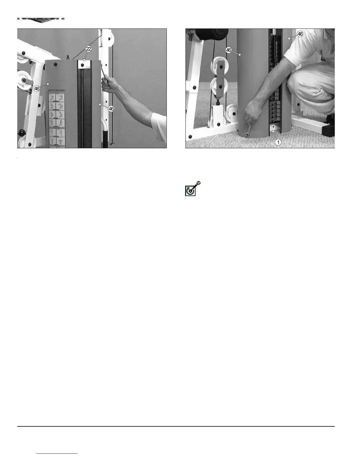
IG. 65 Once you have adjusted the cables according to the Cable
djustment Diagram on the previous page, then locate the two Weight
hrouds (#46) and affix them to the Guide Rod Retainer Housing’s
20) U-Nuts 1/4” (#81-Not shown) using four Hex Head Cap Screws 1/4-
X 3/4 (#105), and four Nylon Flat Washers 1/4” (#78). Refer to the Ex-
loded View Diagram on Fold out page for further illustration of this as-
mbly.
FIG. 66 Next, affix the bottom of the two Weight Shrouds (#46) to th
Base Frame’s (#1) U-Nuts 1/4” (#81-Not shown) using four Hex He
Cap Screws 1/4-20 X 3/4 (#105), and four Nylon Flat Washers 1/4” (#89
Refer to the Exploded View Diagram on Fold out page for further illustr
tion of this assembly.
Fully Fasten:Proceed to align and fully fasten these hardware a
semblies.
23 TS-1000 Home Gym w/Adjustable High-Low Pulley Syste