Table of Contents
1、Shape drawing ........................... ........................ ..........1
2. Main technical parameters .................. ................2
3. Use and scope of use ........................... ............. .... 3
4. Instructions for use and operation ............ ... .. 3
4.1 Power switch ........................... .............................. .........4
4.2 Combination lock ........................... .............................. 4
4.3 Handle Monitor ........................... ...................................5
4.4 Emergency reverse switch ........................... ................6
4.5 Do not overload use, the maximum load is 2000KG .......6
4.6 Travel and Braking ........................... ..............................7
4.7 Charging jack ........................... ......................................8
4.8 Vehicle travel steering ........................... .................. 9
4.9 Scale ....................... ............. .... ................... .................10
5. Battery use and maintenance ..............................13
6. Fault code ........................... ................................... ..........14
7. Hydraulic schematics ..................................................15
8. Electrical schematics ........................... .......................16
9. Packaging, shipping ........................... .........................17
10. Warning (Caution) ........................... .............................17
11. Handle assembly ........................... ..............................19
12. Driver components ........................... .........................20
13. Front frame assembly .................... ......................... 21
14. Connecting rod assembly ........................... .......... 22
15. Rear frame assembly ........................... ....... ..............23
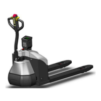
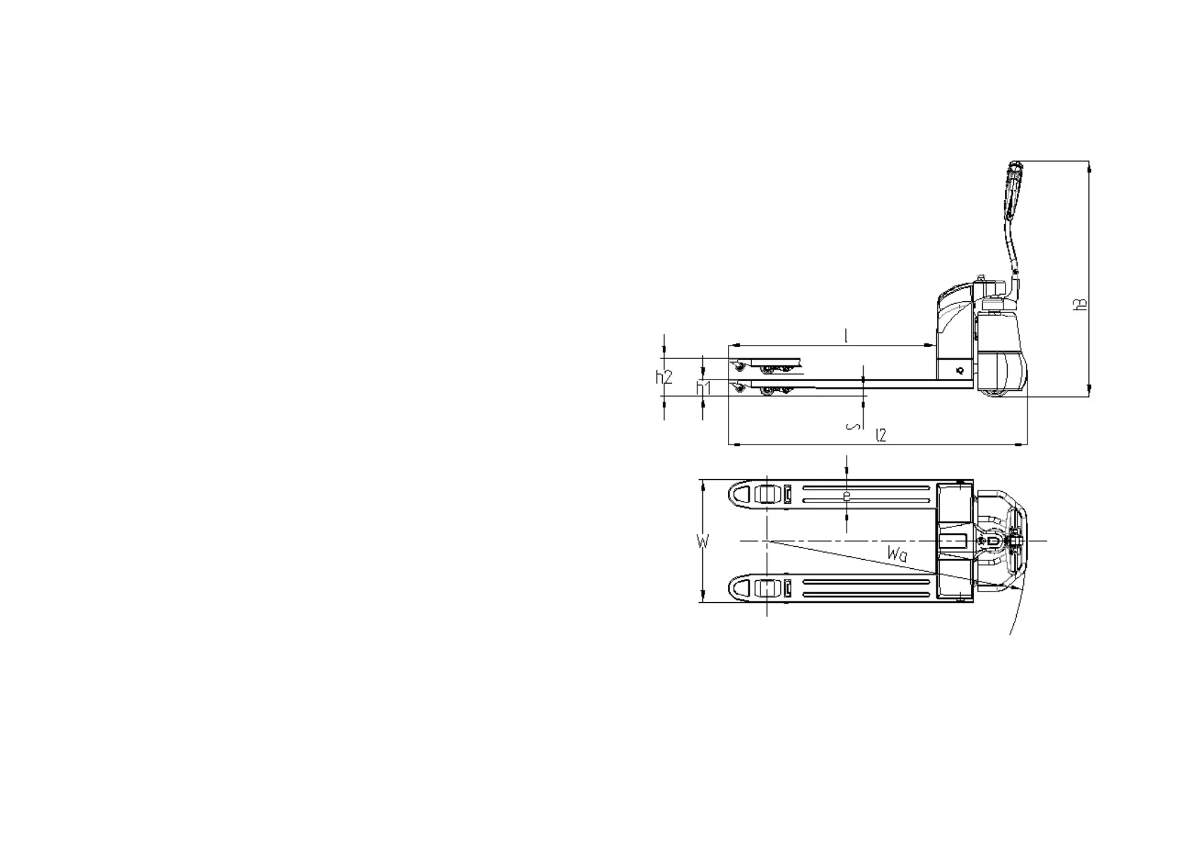
1. Shape drawing
Figure 1-1
1