3
240064-1
MODELS
Each letter of the model number identi es an oven feature followed by a number that
identi es the capacity of the model.
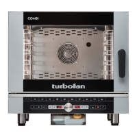
EC40D5 = Turbofan Combi Oven Electric - 5 Tray Digital.
EC40D7 = Turbofan Combi Oven Electric - 7 Tray Digital.
EC40D10 = Turbofan Combi Oven Electric - 10 Tray Digital.
EC40M5 = Turbofan Combi Oven Electric - 5 Tray Manual.
EC40M7 = Turbofan Combi Oven Electric - 7 Tray Manual.
EC40M10 = Turbofan Combi Oven Electric - 10 Tray Manual.
CAPACITY
Page
1 • GENERAL REMINDERS 4
2 • TECHNICAL DATA 5
3 • SPECIAL REQUIREMENTS FOR THE INSTALLATION SITE 6
4 • STATUTORY REQUIREMENTS, TECHNICAL REGULATIONS AND DIRECTIVES 6
5 • POSITIONING 7
6 • ELECTRICAL CONNECTIONS AND EQUIPOTENTIAL BONDING 8
7 • POINTS TO REMEMBER WHEN MAKING THE ELECTRICAL CONNECTION 9
8 • WATER AND DRAIN CONNECTIONS 10
9 • VENTS 10
10 • COMMISSIONING AND TESTING 11
11 • IMPORTANT INFORMATION FOR THE USER 11
12 • DISMANTLING AND DISPOSAL 12
13 • INSTALLATION DIAGRAMS 13
14 • REMOVING THE CONTROL PANEL (VERSION D) 14
CONTENTS
The reproduction or copying of any part of this manual by any means
whatsoever is strictly forbidden unless authorized previously in writing by
the manufacturer.
- ORIGINAL INSTRUCTIONS -
The manufacturer accepts no liability for any inaccuracies in this manual
attributable to printing or copying errors. We reserve the right to modify
our products as we deem fit, without impairing their basic features.
EC40D5 / M5 5 x GN 1/1 - 5 x 600 x 400
EC40D7 / M7 7 x GN 1/1 - 7 x 600 x 400
EC40D10 / M10 10 x GN 1/1 - 10 x 600 x 400
 Loading...