Page 3 of 9
General Description
Both types can be supplied with automatic reversing (Style “R”), feature steam jackets (through which steam or other heating medium
may be forced to melt or reduce viscosity of materials to permit rotation of the pump at starting. Conversely, when desirable, cooling
water may be forced through these jackets). These pumps can also be supplied with an integral relief valve. Nitrile, Neoprene and Viton
seals are available with these units along with P.T.F.E. or Mellinex gaskets. When pumping temperatures in excess of 1000c are used,
special H.T. gaskets are also available.
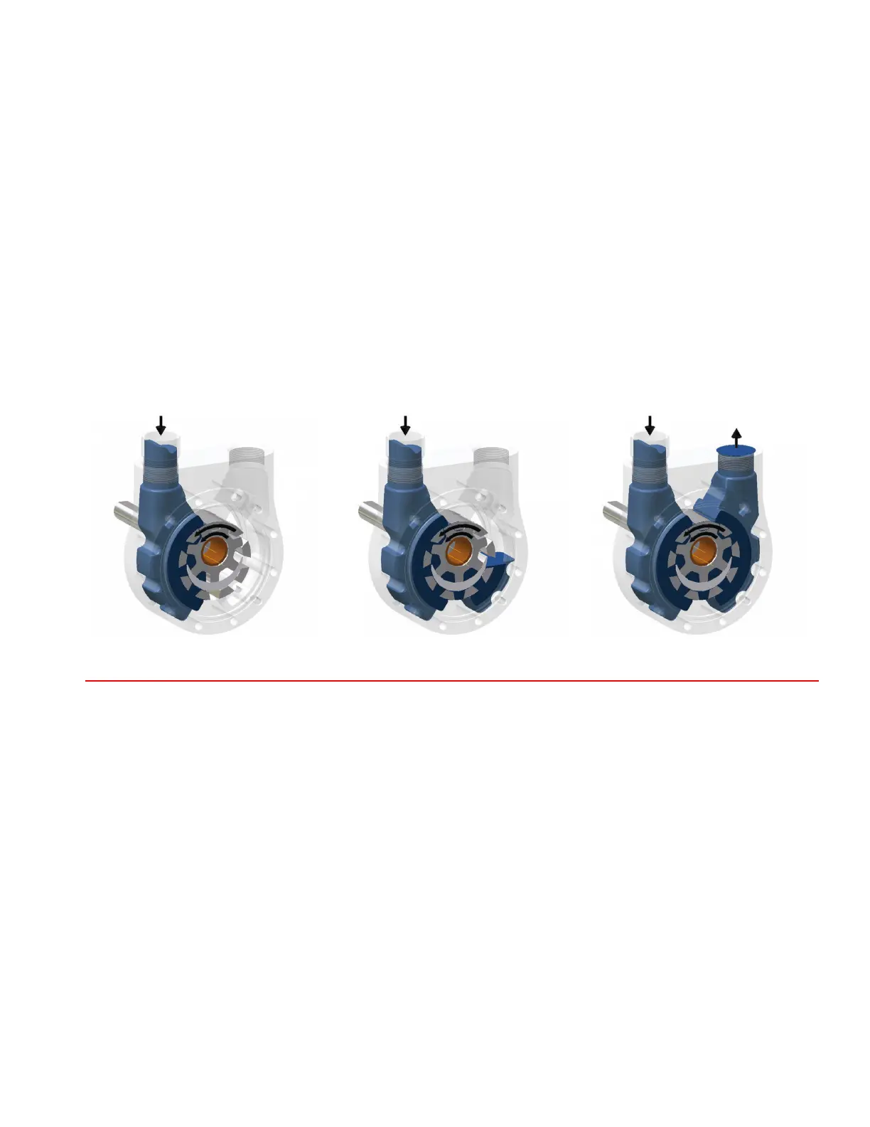
The Pumping Principle
Tuthill internal-gear principle is based upon the use of a rotor, idler gear and crescent shaped partition that is cast integrally with the
cover. (See accompanying gure). Thus, only two moving parts comprise this ecient pumping element. Power is applied to the rotor
and transmitted to the idler gear with which it meshes. The space between the outside diameter of the idler and the inside diameter of
the rotor is sealed by the crescent. When the pump is started, there is an increase in volume as the teeth come out of mesh. This creates
a partial vacuum, drawing the liquid into the pump through the suction port. The liquid lls the space between the teeth of the idler and
rotor and is carried past the crescent partition to the pressure side of the pump. When the teeth mesh on the pressure side, the liquid
is forced from the spaces and out through the discharge port.
WARNING
Failure to follow these instructions could result in serious bodily injury or death. These pumps should not be used for handling plain
water, corrosive/abrasive liquids, or liquids not possessing adequate lubricity. Do not attempt to work on any Tuthill pump installation
before completing the steps below. Disconnect the drive so that it cannot be started while work is being performed. Review the Material
Safety Data Sheet (MSDS) applicable to the liquid being pumped to determine its characteristics and the precautions necessary to
ensure safe handling. Vent all pressure within the pump through the suction or discharge lines. All Tuthill pumps contain residual ISO
32 lube oil from the factory production test. Determine if this is compatible with the uid you are pumping. If the uid is incompativle
please consult factory directly.
Location
The pump should be located as close to the source of supply as conditions will permit, below the level of the liquid in the reservoir, if
possible. Pumps should be located in a dry and clean place, with space to work around them.
When necessary to locate pumps in pits, provisions should be made to safeguard against oods. Care must be taken to properly support
the suction and discharge piping so that no strain can be put on the pump from either its weight or expansion. Piping strains are very
often the cause of misalignment, hot bearing, worn couplings and vibrations.