29
17. Install spacer [67] on each shaft. Install oil slinger [21] on lower rotor, (either shaft on vertical ow units)
spacer [57] on opposite shaft, washers [25], and screws [29]. Lay assembly down with drive on left for
timing.
8.2.5 ADJUSTING ROTOR INTERLOBE CLEARANCE:
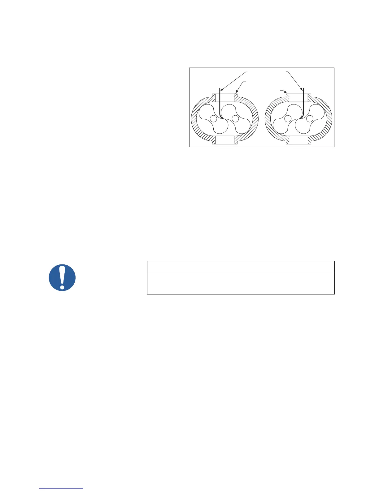
18. Using feeler gauges take interlobe readings
and record on each side of housing as
indicated in Figure 10. By removing or
adding shim behind the helical gear, it rotates
as it is moved in or out and the driven rotor
turns with it, thus changing the clearance
between rotor lobes.
Changing the shim thickness .006” (.15 mm)
will change the rotor lobe clearance .003”
(.08 mm) or one-half the amount.
EXAMPLE: Referring to Figure 10 to the
right, check the clearance a AA (right hand reading) and BB (left hand reading). If AA reading is .009”
(.23 mm) and BB reading .003” (.08 mm) by removing .006” (.15 mm) shims, the readings will change
one-half the amount removed or .003” (.08 mm) AA should then read .006” (.15 mm) and BB should
read .006” (.15 mm). The nal reading should be within .002” (.05 mm) of each other.
To determine the amount of shim to add or remove, subtract the small gure from the larger. If the
right side reading is higher than the left side, remove shim. If the right side reading is lower, add shim.
19. Install drive shaft [45] and secure with Allen screws [66]. Check drive shaft runout behind keyway. Do
not exceed .002” (.05 mm) T.I.R. Install lockwire [49].
20. Remove temporary cap screws from gear end plate and apply a bead of sealer around end plate (not
cover), encircling all holes, and install gear cover [6] and secure with cap screws [26A].
NOTE
If cooling coil or ttings were disturbed or water was detected in drain oil,
they should be retested with air pressure to check for leaks and resealed.
This applies to mechanical seal series only.
8.2.6 DRIVE SHAFT SEAL ASSEMBLY:
21. Install cover [6].
22. Install new mechanical seal [76] into seal housing [91], and press in lip seal [13].
23. Install mating ring [76] onto drive shaft and install assembled seal housing.
24. Be sure to lubricate seals before nal assembly.
8.2.7 COMPLETE BOOSTER ASSEMBLY:
25. Install free end cover [7] following the same procedure used to install the gear cover. Secure with cap
screws [26B].
26. Apply sealer and install both port ttings [38 or 48].
27. Install all necessary cooling water lines.
28. Prior to putting booster into operation, follow instructions stated within the Installation and Operation
sections. Observe the oil level frequently during the initial hours of operation. An improperly installed
or damaged oil seal will result in oil loss.
A
BB
B
A
B
A
A
A
A
B
A
B
B
A
B
RECORD A-A
READING HERE
RECORD B-B
READING HERE
Figure 10 - Checking Rotor Interlobe Clearance
 Loading...