Page 13 of 20
TFP1350
ALARM SWITCH
SOLENOID VALVE
E4
NOTES:
Electric Actuation Trim is comprised
All Fittings and Nipples are
galvanized (Standard Order).
of Items 1-32 plus E1-E4.
CH1..............Bushing
E2 1/2" Tubing Connector CH1..
E4
E3 1
21/2" x 1-1/2" Nipple
1/2" x 24" Tubing
.....
.......
CH
CH
2.
27
31
E1
32
29
30
28
23
25
26
24
22
21
CH1........1/2" x 2" Nipple
1
1
1
1
1
1
........1/4" x 3" Nipple
1-1/4" x 3" Nipple
1/2" 90° Elbow . . . . . . . . .
.......
1/2" x 2-1/2" Nipple
1/2" x 3-1/2" Nipple
1/2" x 4-1/2" Nipple
.....
.....
.....
CH
CH
CH
1.
CH
CH
CH
6
4
5
1
2
18
..............1/2" Tee
1/2" x 1-1/2" Nipple
1/2" x 1/4" x 1/2" Tee
1/2" x 1/2" x 3/4" Tee . . . .
.....
....
............
1/2" 90° Elbow
1/2" Union
.........
CH
CH
CH
CH
CH
CH
8 Priming Supply
13
17
19
20
18
15
16
14
12
11
9
10
...........1Drip Funnel 92-343-1-007
1
1
1
1
1
1
.......1/2" x 24" Tubing
.............
.............
1/2" x 1/4" Reducing
3/4" Plug
1/4" Plug
3/32" Vent Fitting
1/4" x 24" Tubing
1/2" Tubing Connector
.......
..
.......
CH
CH
CH
92-032-1-002
CH
CH
1
1
1
1
1
...........Drain Valve
Drip Funnel Bracket
Drip Funnel Connector
....
..
............
1/2" Y-Strainer
Model AD-1 Automatic
Restriction
.........
52-793-2-004
92-211-1-003
92-211-1-005
52-353-1-005
92-020-1-009
3
7
6
4
5
2
1
NO.
Model MC-1 Manual
1
1
1
1
2
1/2" Swing Check Valve
1/2" Spring Loaded
Check Valve . . . . . . . . . .
..
1-1/4" Angle Valve
Control Station
1/2" Ball Valve
......
.........
.........
46-049-1-004
92-322-1-002
52-289-2-001
46-048-1-007
46-050-1-004
2
1
QTY.
1/4" Gauge Test Valve
300 psi/ 2000 kPa
Water Pressure Gauge . .
..
DESCRIPTION
92-343-1-005
46-005-1-002
P/N
See Figure 1 for Valve Port4.
Route all Tubing to Drip Funnel.
identification.
5.
CH: Common Hardware.
26
31
2
18
28
3.
22
20
1
4
22
16
21
26
13
26
6
10
11
12
23
23
26
27
26
17
26
26
24
3
32
30
23
29
23
26
26
521
2626
26
26
23
22
22
15
5
(GREEN
TINT)
14
21
1
26
22
8
7
E4
(ORDERED
SEPARATELY)
E2
E3
9
E1
26
21
26
26
24
N.O. ALARM
(BVS-3/4")
CONTROL VALVE
ELECTRICALLY
SUPERVISED
FOR OPTIONAL
26
25
22
19
LOCATION
(ORDERED
SEPARATELY)
PRESSURE
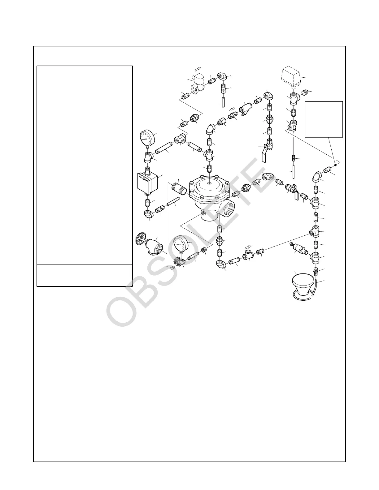
FIGURE 9
2-1/2 INCH (DN65) MODEL DV-3 DELUGE VALVES
— EXPLODED VIEW OF ELECTRIC ACTUATION TRIM (52-445-2-103) —
(Refer to Figure 12 to see the factory assembled trim segments,
as well as functional callouts of the trim components)