TFP1410
Page 10 of 14
NOTES: Wet Pilot Lines must be main-
tained at a minimum temperature of
40°F (4°C).
At a minimum, it is recommended that
internally galvanized pipe and cast iron
fittings be used for wet pilot lines.
System Air Pressure Requirements
The supervisory air (nitrogen) pressure
is to be 10 ± 2 psi (0,69 ± 0,14 bar). The
use of a higher supervisory pressure
is subject to approval by the author-
ity having jurisdiction, and it should be
understood that the use of a higher su-
pervisory pressure may increase water
delivery time. The use of a lower su-
pervisory pressure may prevent clear-
ing the alarm of the Supervisory Low
Pressure Alarm Switch (Item P3 - Fig.
3A), which is factory set to alarm at 5
± 1 psi (0,34 ± 0,07 bar) on decreas-
ing pressure. The supervisory air sup-
ply pressure of 10 ± 2 psi (0,69 ± 0,14
bar) can be provided by any of the fol-
lowing methods. Refer to the applica-
ble data sheet for laboratory approval
information.
•
Model G16AC812 (self-contained)
Automatic Supervisory Air Supply
described in Technical Data Sheet
TFP1620.
• A maximum 200 psi (13,8 bar) plant
air supply in combination with the
Model AMD-1 Air Maintenance De-
vice described in Technical Data
Sheet TFP1221.
• A maximum 3000 psi (206,9 bar) ni-
trogen cylinder in combination with
the Model AMD-3 Nitrogen Mainte-
nance Device described in Technical
Data Sheet TFP1241.
NOTE: The dew point of the air or ni-
trogen supply for a system exposed to
freezing conditions must be maintained
below the lowest ambient temperature
to which the system piping will be ex-
posed. Introduction of moisture into
the system piping can create ice build
up that could prevent proper operation
of the system.
The Supervisory Low Pressure Alarm
Switch (Item P3 - Fig. 3A) is factory set
at 5 ± 1 psi (0,34 ± 0,07 bar) on de-
creasing pressure. The Pressure Relief
Valve (Item P4- Fig. 3A) is factory set to
fully open at 25 ± 2 psi (1,72 ± 0,14 bar)
and it begins to crack open at a pres-
sure of about 18 psi (1,24 bar).
Friction Loss
The nominal pressure loss versus ow
data for the DV-5 Deluge Valve plus
Riser Check Valve is provided in Graph
A.
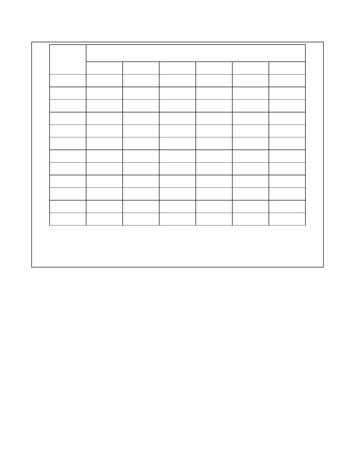
Supply
Pressure,
(1)
PSI
(Bar)
Maximum Pilot Height,
(2)
Feet
(Meters)
1-1/2"
(DN40)
2"
(DN50)
3"
(DN80)
4"
(DN100)
6"
(DN150)
8"
(DN200)
20
(1,4)
7
(1,4)
3
(0,9)
7
(1,4)
17
(5,2)
18
(5,5)
9
(2,7)
40
(2,8)
24
( 7,3)
19
(5,8)
30
(9,1)
39
(11, 9)
38
(11,6 )
38
(11,6 )
60
(4,1)
46
(14,0)
38
(11,6 )
52
(15,8)
54
(16,5)
56
(17,1)
44
(13,4)
80
(5,5)
58
(17, 8)
54
(16,5)
70
(21,3)
60
(18,3)
70
(21,3)
58
(17, 8)
100
(6,9)
78
(23,8)
78
(23,8)
93
(28,3)
78
(23,8)
99
(30,2)
65
(19,8)
120
(8,3)
87
(26,5)
87
(26,5)
117
(35,7)
115
(33,1)
130
(39,6)
96
(29,3)
140
(9,7)
105
(32,0)
107
(32,6)
139
(42,4)
142
(43,3)
154
(46,9)
141
(43,0)
160
(11,0 )
127
(38,7)
123
(37, 5)
161
(4 9,1)
176
(53,6)
161
(4 9,1)
170
(51,8)
175
(12,1)
134
(40,8)
138
(42,1)
172
(52,4)
171
(52,1)
194
(59,1)
194
(59,1)
200
(13,8)
160
(48,8)
160
(48,8)
206
(62,8)
223
(68,0)
216
(65,8)
206
(62,8)
225
(15,5)
185
(56,4)
166
(50,6)
237
(72,2)
233
(71,0)
246
(75,0)
250
(76,2)
250
(17, 2)
201
(61,3)
199
(60,7)
251
(76,5)
247
(75,3)
275
(83,8)
257
(78,3)
NOTES:
(1)
If supply pressure is variable, assume minimum expected value.
(2)
Maximum pilot height for up to 500 feet (150 meters) of equivalent length of pilot line (pipe plus ttings).
(3)
Interpolation between data points is permitted.
TABLE A
1-1/2 THRU 8 INCH (DN40 THRU DN200) DV-5 WET PILOT DESIGN CRITERIA FOR UP TO
500 FEET OF EQUIVALENT LENGTH OF PILOT LINE (PIPE PLUS FITTINGS)
 Loading...


