TFP1410
Page 4 of 14
NOTICE
The DV-5 Supervised Single Interlock
Preaction System with Wet Pilot Actua-
tion Trim described herein must be in-
stalled and maintained in compliance
with this document, as well as with the
applicable standards of the National
Fire Protection Association, in addition
to the standards of any other authori-
ties having jurisdiction. Failure to do so
may impair the performance of the re-
lated devices.
The owner is responsible for main-
taining their fire protection system
and devices in proper operating con-
dition. Contact the installing contrac-
tor or product manufacturer with any
questions.
Technical
Data
Approvals
UL and C-UL Listed
Deluge Valve
DV-5
Riser Check Valve
Model CV-1FR
NOTE: 1-1/2 inch (DN40) risers utilize
a 2 inch (DN50) Model CV-1FR Riser
Check Valve connected to the 1-1/2
inch (DN40) DV-5 Deluge Valve by a
2 x 1-1/2 inch Figure 716 Reducing
Coupling.
Valve Trim
The Supervised Single Interlock Pre-
action System with Wet Pilot Actuation
Trim (Fig. 3A or 3B) forms a part of the
laboratory listings and approvals. The
trim is necessary for proper operation
of the DV-5 Valve.
Each package of trim includes the fol-
lowing items:
• Water Supply Pressure Gauge
• Diaphragm Chamber
Pressure Gauge
• Diaphragm Chamber Connections
• Manual Control Station
• Main Drain Valve
• System Drain Valve
• Alarm Test Valve
• Automatic Drain Valve
• System Air Pressure Gauge
• Air Supply Connections
•
Low Air Pressure Supervisory Switch
•
Waterow Pressure Alarm Switch
(PS10-2)
The following items are included in the
Pre-trimmed Valve Assembly and can
be ordered separately for the valve
trim:
• Model BFV-N Buttery Valve
• Figure 577 Grooved Coupling
To ease eld assembly of the trim ar-
rangement, the trim components are
provided partially assembled as shown
in Figure 3B.
The trim arrangement is provided with
galvanized or black nipples and ttings.
The galvanized trim is intended for
non-corrosive or corrosive conditions,
whereas the black trim is principally in-
tended for use with AFFF systems.
NOTE: When the system pressure is
greater than 175 psi (12,1 bar), provi-
sion is to be made to replace the stan-
dard order 300 psi (20,7 bar) Water
Pressure Gauges, shown in Figure 3A
or 3B with separately ordered 600 psi
(41,4 bar) Water Pressure Gauges.
Detection System
In order for a single interlock preaction
system to be hydraulically calculated
as a wet pipe system, as opposed to a
dry pipe sprinkler system, the detection
system must be designed to operate
sooner than the automatic sprinklers
on the sprinkler piping. In the case of
wet pilot actuation, the system design-
er selects pilot sprinklers that will op-
erate sooner than the automatic sprin-
klers chosen for use on the sprinkler
piping.
The Supervised Single Interlock Pre-
action System with Wet Pilot Actua-
tion Trim provides for connection of a
detection system consisting of Wet Pi-
lot Line Sprinklers (heat detectors) and
manual control stations interconnected
with minimum 1/2 inch (DN15) Sched-
ule 40 steel pipe. The pilot line is con-
nected to the Wet Pilot Detection con-
nection shown in Figure 3B. Nominal
installation dimensions for the Super-
vised Single Interlock Preaction Sys-
tem with Wet Pilot Actuation Trim are
shown in Figure 4.
Wet pilot sprinklers are to be minimum
5.6 K-factor orice listed or approved
automatic sprinklers. Manual Control
Stations are to be the Model MC-1
described in Technical Data Sheet
TFP1382.
The maximum height of a wet pilot line
above the DV-5 Valve must not exceed
the limitations shown in Table A as a
function of the minimum water sup-
ply pressure to the DV-5 Valve for an
equivalent length (pipe plus ttings) of
the pilot line up to 500 feet to the most
remote pilot sprinkler.
Provision must be made for installing
a 5.6 K-factor orice, Inspector’s Test
Connection at the most hydraulically
demanding location of a wet pilot line
(usually adjacent to the highest and
most remote wet pilot line sprinkler or
manual control station).
Continued on Page 10
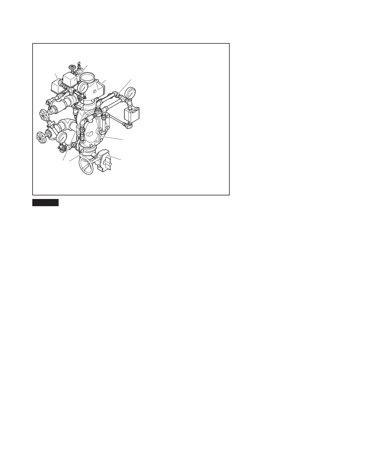
NOTES:
1. SEE FIGURE 3, PER VALVE SIZE
AS APPLICABLE, FOR TRIM
ARRANGEMENT WITH BILL OF
MATERIALS AND COMPONENT
PART NUMBERS.
TRIM SHOWN FULLY ASSEMBLED;
COMPONENTS SUCH AS GAUGES
AND SWITCHES MAY REQUIRE
ASSEMBLY IN TRIM AT VALVE
INSTALLATION.
2.
DV-5
DELUGE
VALVE
WATERFLOW
PRESSURE
ALARM
SWITCH
SYSTEM
SHUT-OFF
VALVE
PREACTION
SINGLE
INTERLOCK
WET PILOT
ACTUATION
TRIM
GROOVED
COUPLING
PRESSURE
ALARM
SWITCH
CHECK
VALVE
FIGURE 2
DV-5 PRE-TRIMMED SUPERVISED SINGLE INTERLOCK
PREACTION SYSTEM, WET PILOT ACTUATION
 Loading...


