TFP1484
Page 10 of 16
Installation
DV-5 Preaction Type A Valves are to
be installed in accordance with this
section.
General Instructions
Proper operation of the DV-5 Pre-
action Type A Valve depends upon
installation in accordance with the
instructions given in this technical data
sheet. Failure to follow the appropriate
steps may prevent the DV-5 Valve with
Preaction Type A Trim from function-
ing properly, may void the manufactur-
er’s warranty, and will void listings and
approvals.
The DV-5 Preaction Type A Valve must
be maintained at a minimum tempera-
ture of 40°F (4°C).
NOTICE
Heat tracing of the DV-5 Preaction Type
A Valve is not permitted. Heat tracing
can result in the formation of hardened
mineral deposits that are capable of
preventing proper operation.
Notes:
• Install the valve in a readily visible and
accessible location.
• Ensure the fully assembled Preaction
Type A Trim is installed in accordance
with Figure 3.
• Ensure suitable provision for disposal
of drain water. Direct drainage water so
that it will not cause accidental damage
to property or danger to persons.
Step 1. Connect the Diaphragm
Chamber Supply Control Valve to the
inlet side of the system’s Main Control/
Shut-off Valve in order to facilitate
setting of the Preaction Type A Trim
(Ref. Figures 3, 5 and 6).
Step 2. Install a suitable automatic
supervisory air (nitrogen) supply,
as described in the Technical Data
section, in accordance with the refer-
enced Technical Data Sheet. Set the
device according to Graph B.
Step 3. Install a desiccant dryer, when
required for the supervisory air supply,
between a drip leg and the Model
AMD-1 Air Maintenance Device or
between the Automatic Supervisory Air
Supply and the Preaction Type A Trim.
Step 4. Wire the Supervisory Low Pres-
sure Alarm Switch to the supervisory
alarm initiating circuit of an alarm panel.
Step 5. Make conduit and electrical
connections in accordance with the
requirements of the authority having
jurisdiction.
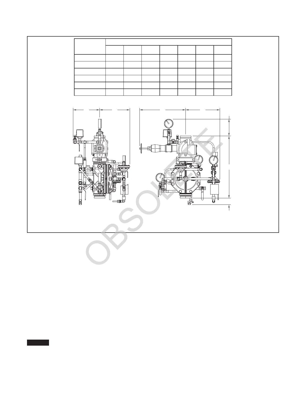
Nominal
Valve Size
Nominal Dimensions in Millimeters
A B* C* D E* F* G
DN40 376 346 356 236 323 221 178
DN50 390 346 356 243 316 221 155
DN80 536 432 356 276 284 184 111
DN100 645 478 356 314 275 176 68
DN150 759 500 356 380 286 140 36
DN200 936 529 406 420 309 88 N/A
*
Minimum Clearance
E D B C
F
A
G
FIGURE 4
DV-5 PREACTION TYPE A VALVE
NOMINAL INSTALLATION DIMENSIONS
 Loading...


