TFP1484
Page 3 of 16
Detail Part Material Qty.
1 Body
Ductile
Iron
1
2 Cover
Ductile
Iron
1
3
Cover
Gasket
Nitrile
Rubber
1
4
Hex Cap
Screw
Steel, Zinc
Plated
AR
5 Clapper
Stainless
Steel
1
Detail Part Material Qty.
6
Clapper
Facing
EPDM
Grade “E”
1
7 Spring
Stainless
Steel
1
8
Hinge
Shaft
Stainless
Steel
1
9
Retaining
Ring
Stainless
Steel
AR
11
Retention
Bolt
Stainless
Steel
1
Detail Part Material Qty.
13
Retaining
Disc
Stainless
Steel
1
14 Locknut
Stainless
Steel
1
15 Adhesive
Thread
Sealer
AR
16 Nameplate Aluminum 1
17 Rivet Steel 2
1
Qty.
1
1
4
4
8
8
2
2
4
4
6
6
6
. . . . . . .
. . . . . . . . . . .
. . . . . . . . . . .
. . . . . . . . . . . . . . . . .
. . . . . . . . . . . . . . . . .
. . . . . . . . . . . . . . . . .
. . . . . . . . . . . . . . . . .
. . . . . . . . . . . . . .
. . . . . . . . . . . . . .
. . . . . . . . . . . . . .
. . . . . . . . . . . . .
. . . . . . . . . . . . .
. . . . . . . . . . . . .
. . . . . . . . . . . . . . . . .
. . . . . . . . . . . . . . . . .
. . . . . . . . . .
. . . . . . . . . .
. . . . . . . . . .
. . . . . . . . . .
. . . . . . . . . .
4
1
2
3
(a)
6
5
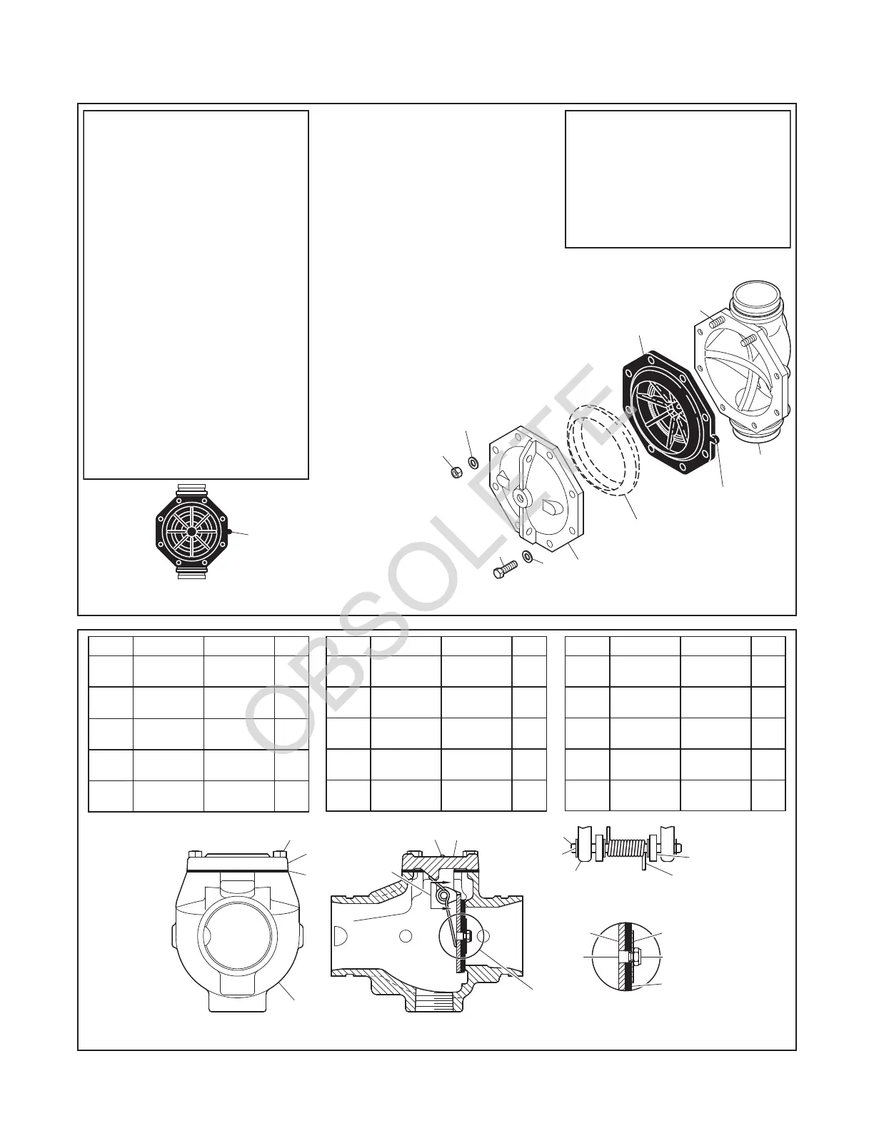
Diaphragm Cover NR
Flat Washer:
No. Description Repair Parts
(a)
Valve Body
Diaphragm
NR
VALVE PARTS
DN40 Valve,
M12 CH
DN50 & DN80 Valve,
M16
DN100 & DN150 Valve,
CH
M16
DN200 Valve,
M20
CH
CH
No. Description P/N
REPLACEMENT PARTS
Diaphragm Kit,
92-477-1-105DN40 Valve
92-477-1-107DN50 Valve
92-477-1-109DN80 Valve
92-477-1-101DN100 Valve
DN150 Valve 92-477-1-103
DN200 Valve 92-477-1-111
Includes Item 2:
Hex Nut:
DN100 & DN150 Valve,
M16 CH
DN200 Valve,
M20 CH
Hex Bolt:
DN40 Valve,
M12 x 30 mm CH
DN50 & DN80 Valve,
M16 x 50 mm
DN100 Valve,
CH
M16 x 50 mm
DN150 Valve,
CH
M16 x 55 mm
DN200 Valve,
CH
M20 x 70 mm CH
ORIENT
DIAPHRAGM TAB
PERPENDICULAR
TO VALVE BODY
CENTERLINE
DIAPHRAGM
ORIENTATION
TAB
6
(NOTE 3)
STUDS
(NOTE 3)
2
(NOTE 4)
V-RING
(NOTE 4)
4
3
5
1
4
1.
2.
3.
4.
Valve Bodies of DN100, DN150 & DN200
valves are equipped with studs and Valve
Covers are secured by Hex Nuts and Hex
Bolts.
V-Ring is attached to Diaphragm of DN100,
DN150 & DN200 valves at factory. If, during
internal valve inspection, V-Ring is
discovered to be detached from Diaphragm,
be advised that V-Ring is a required valve
component and that detachment will not
affect normal valve operation or
performance. Should V-Ring become
detached, reinstall between Diaphragm
and Diaphragm Cover concentrically as
shown.
NR - Not Replaceable
CH - Common Hardware
NOTE: Do not apply adhesives, lubricants,
or other substances to Diaphragm, V-Ring,
or Valve Body.
SEE
VIEW A
SEE
3
2
2
9
7
13
14,15
6
5
11
VIEW A
FIGURE 1
DV-5 VALVE ASSEMBLY
FIGURE 2
MODEL CV-1FR CHECK VALVE ASSEMBLY
 Loading...


