TFP720
Page 7 of 10
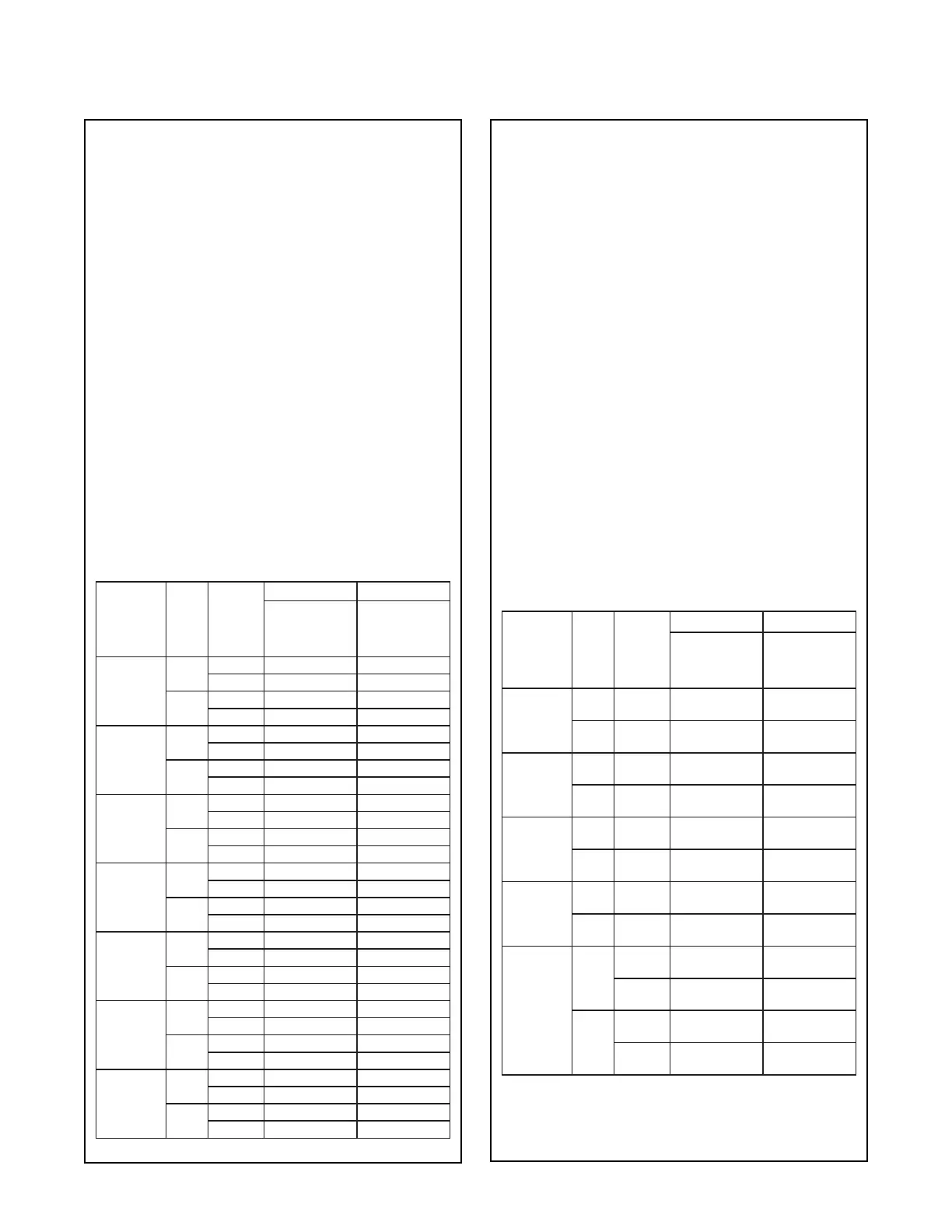
FM - Design Criteria
• Refer to Table A for Model, Nominal Assembly
Length, and Sprinkler Reducer combinations.
• Wet-pipe systems only.
• Maximum service pressure of 12 bar.
• Pendent sprinklers with a maximum K80 (K5.6) for
1/2 inch NPT or maximum K115 (K8.0) for 3/4 inch
NPT.
• Maximum ambient temperature of 107°C for Model
YB25 and YB28.
• These connections are designed for use in ceilings
with grids that meet ASTM C 635 (Standard Specifi-
cation for the Manufacture, Performance, and Test-
ing of Metal Suspension Systems for Acoustical Tile
and Lay-in Panel Ceilings) and ASTM C 636 (Stan-
dard Practice for Installation of Metal Ceiling Sus-
pension Systems for Acoustical Tile and Lay-in
Panels) referenced by IBC. The three structural clas-
sifications are the following: Intermediate-Duty Sys-
tems and Heavy-Duty Systems. These connections
have been approved for use in all Intermediate-Duty
and Heavy-Duty structural classifications.
• Minimum bend radius of 150 mm for Model YB28 or
200 mm for Model YB25.
• FM Friction Loss for YB25 and YB28:
Assembly
Length in
Millimeters
Outlet
(NPT)
Number
of 90°
Bends
YB25 YB28
Equivalent
Length of DN25
Sch. 40 Pipe at
C=120 in Meters
Equivalent
Length of DN25
Sch. 40 Pipe at
C=120 in Meters
700
1/2
0 3,9 1,1*
1 5,7 1,1*
3/4
0 3,9* 1,1*
1 8,3* 1,6*
1000
1/2
0 5,7* 1,7
1 7,5* 1,7
3/4
0 5,7* 1,7
1 9,7* 2,2
1200
1/2
0 6,8* 2,0*
1 8,6* 2,1*
3/4
0 7,1* 2,1*
1 10,6* 2,6*
1500
1/2
0 8,6* 2,5*
1 10,4* 2,7*
3/4
0 9,3* 2,7*
1 12,3* 3,2*
1800
1/2
0 10,3* 3,0*
1 12,1* 3,2*
3/4
0 11,0* 3,2*
1 14,4* 3,8*
2000
1/2
0 11,5* 3,3*
1 13,3* 3,6*
3/4
0 12,5* 3,6*
1 15,5* 4,2*
2500
1/2
0 14,4 4,1
1 16,2 4,6
3/4
0 16,2* 4,6
1 18,3* 5,2
*Approximate value based on interpolation and extrapolation.
UL - Design Criteria
• Refer to Table A for Model, Nominal Assembly
Length, and Sprinkler Reducer combinations.
• Wet-pipe systems only.
• The hose and ttings have limited exibility and are
intended for direct connection to sprinklers in accor-
dance with NFPA 13, 13D, or 13R.
• Maximum service pressure of 13 bar.
• Pendent sprinklers with a maximum K80 (K5.6) for
1/2 inch NPT or maximum K115 (K8.0) for 3/4 inch
NPT.
• Maximum ambient temperature of 107°C for Model
YB25 and YB28, or maximum ambient temperature
of 148°C for Model YN25.
• These connections are designed for use in ceilings
with grids that meet ASTM C 635 (Standard Specifi-
cation for the Manufacture, Performance, and Test-
ing of Metal Suspension Systems for Acoustical Tile
and Lay-in Panel Ceilings) and ASTM C 636 (Stan-
dard Practice for Installation of Metal Ceiling Sus-
pension Systems for Acoustical Tile and Lay-in
Panels) referenced by IBC. The three structural clas-
sifications are the following: Intermediate-Duty Sys-
tems and Heavy-Duty Systems. These connections
have been approved for use in all Intermediate-Duty
and Heavy-Duty structural classifications.
• Minimum bend radius of 76 mm.
Assembly
Length in
Millimeters
Outlet
(NPT)
Maximum
Number
of 90°
Bends*
YN25 and YB25 YB28
Equivalent
Length of DN25
Sch. 40 Pipe at
C=120 in Meters
Equivalent
Length of DN25
Sch. 40 Pipe at
C=120 in Meters
700
1/2 2 6,7 3,0
3/4 2 8,5 4,9
1000
1/2 2 9,8 4,9
3/4 2 11,6 7, 0
1200
1/2 2 12,5 6 ,1
3/4 2 14,6 7,6
1500
1/2 2 14,9 7,0
3/4 2 16,5 8,5
1800
1/2
2 18,3 7, 9
3 20,4 9,8
3/4
2 20,4 10,1
3 22,6 11,6
* Information in this column indicates the maximum number of
allowable bends and that hoses are installed with at least one bend.
 Loading...