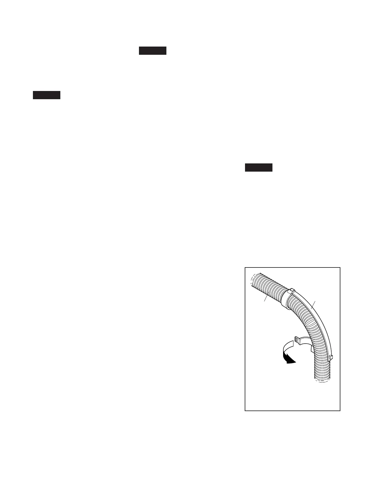
FIGURE 4
MINIMUM RADIUS INDICATOR
MRI55
TFP720
Page 8 of 10
Installation
The Tyco
®
FASTFLEX Flexible Sprin-
kler Hose as shown in Figure 1, is
to be installed with the following
instructions.
NOTICE
Flexible Hoses are intended only to
connect sprinklers directly to system
piping; for an example, refer to Figure
1. Flexible Hoses cannot be joined to-
gether to form longer hoses. Joining
Flexible Hoses together creates an as-
sembly with “unknown performance”
that has not been accounted for in
system calculations or safe product
performance.
Step 1. Review the Design Criteria
section that applies to the Approval
agency recognized by the authority
having jurisdiction, as well as Figure 3
that provides “Installation Guidance”.
Step 2. Determine the approximate
place where the sprinkler will be locat-
ed. The Support Bar is 700 mm long
and shall be mounted on the 600 mm
width of the ceiling grid. The sprinkler
should be located as close as possible
to the center of the distance between
ceiling grid t-bars.
Step 3. Slide the Reducer Bracket
onto the Support Bar. Loosely attach
the Reducer Bracket and the two Bar
Fixing Clamps on the Support Bar and
place the Bar Fixing Clamps such that
the Support Bar crosses the location
where the sprinkler will be located.
Step 4. Attach one end of the Flexible
Hose onto the sprinkler reducer. Ap-
plying the wrench to the Slip Nut, and
not to the Flexible Hose, tighten to a
maximum torque of 35 Nm.
Step 5. Attach the Inlet Nipple on to
the branch line. Ensure that the arrow
is in the appropriate direction of flow
to the sprinkler and to use pipe thread
sealant at the connection to the branch
line.
Attach one end of the Flexible Hose on
to the Inlet Nipple. Applying the wrench
to the Slip Nut, and not to the Flexible
Hose, tighten to a maximum torque of
35 Nm. Do not twist the Flexible Hose.
Step 6. Bend the Flexible Hose into a
curve(s) that locates the Sprinkler Re-
ducer at the other end of the Flexible
Hose in the area where the sprinkler
will be located. The tube arc should
not be twisted, and the arc should be
as large and smooth as possible.
NOTICE
For minimum bend criteria, refer to the
Design Criteria section that applies to
the Approval agency recognized by the
authority having jurisdiction.
A bend radius smaller than provid-
ed by the minimum bend criteria
may adversely effect the friction loss
specifications stated by the approval
laboratory.
For assembly lengths greater than
1800 mm the Flexible Hose shall be
supported to the structure to ensure
that the maximum unsupported length
does not exceed 1800 mm. In these
cases, it is recommended that the
tube be secured to a fixed mounting
point every 600 mm, in order to pro-
vide a more stable installation.
For installations per LPCB, all bends
greater than 45° shall be tted with a
MRI55 Plastic Clip Minimum Radius
Indicator (Refer Figure 4).
Step 7. Insert the Sprinkler Reducer
into the Reducer Bracket. Locate the
Reducer Bracket and Sprinkler Re-
ducer where the sprinkler will be, and
loosely tighten the Butterfly Bolt on the
Reducer Bracket.
Step 8. Attach the sprinkler to the
Sprinkler Reducer. Put a wrench on the
Sprinkler Reducer to counteract the
tightening torque and prevent the Flex-
ible Hose from twisting. Reference the
sprinkler manufacturer’s sprinkler data
sheet for appropriate sprinkler tighten-
ing torque, sprinkler wrench, and other
guidance.
Step 9. Verify that the Sprinkler Re-
ducer is seated in the Reducer Brack-
et. Precisely locate the sprinkler in
all three axes in accordance with the
sprinkler manufacturer’s data sheet.
Tighten the Butterfly Bolts on the Bar
Fixing Clamps and the Reducer Brack-
et. The tightening torque for the Bar
Fixing Clamp fastener is 4,5 to 5,7 Nm,
and the tightening torque for the Re-
ducer Bracket fastener, is a minimum
of 2,3 Nm.
Step 10. After tightening all the But-
terfly Bolts, verify that the sprinkler is
properly located in accordance with
the manufacture’s instructions. If not,
loosen the Butterfly Bolts and readjust
as required.
Care and
Maintenance
The owner is responsible for the in-
spection, testing, and maintenance of
their fire protection system and devic-
es in compliance with this document,
as well as with the applicable stan-
dards of the authorities having jurisdic-
tion. The installing contractor or prod-
uct manufacturer should be contacted
relative to any questions.
It is recommended that automatic sprin-
kler systems be inspected, tested,
and
maintained by a qualified Inspection
Service in accordance with local re-
quirements and/or national codes.
NOTICE
Before closing a fire protection system
control valve for inspection or mainte-
nance work on the fire protection sys-
tem that it controls, permission to shut
down the effected fire protection sys-
tem must first be obtained from the
proper authorities and all personnel
who may be affected by this action
must be notified.
After placing a fire protection system
in service, notify the proper authorities
and advise those responsible for moni-
toring proprietary and/or central sta-
tion alarms.
FLEXIBLE
HOSE
YN25
INDICATOR
RADIUS
MINIMUM
MRI55
 Loading...