TECHNICAL DATA
Deluge Valve:
The 4 and 6 inch (100 and 150 mm),
Model F470H Horizontal Multimatic
Deluge Valves are rated for use at a
maximum service pressure of 175 psi
(12,1 bar). The Valve dimensions are
shown in Figure A, and all of the ports
are NPT threaded per ANSI Standard
B1.20.1. Flanged inlet and outlet con-
nections are available drilled per the
ANSI, AS, ISO, and JIS specification
options indicated in Table A. When the
flange drilling is provided to AS, ISO,
or JIS specifications, the label located
on the Handhole Cover indicates the
specification to which the flange drill-
ing has been provided.
The F470H Valve is to be installedhori-
zontally, as shown in Figure A.Exterior
surfaces of the F470H Valve are
painted red, and the year of manufac-
ture is indicated on the Handhole
Cover.
Components of the F470H Valve are
shown in Figure B. The Body, Hand-
hole Cover, and Diaphragm Cover are
ductile iron per ASTM A536 (UNS
F33100). The Handhole Cover Gasket
is neoprene, and the Clapper Facing,
Diaphragm, and O-Rings are EPDM.
The Seat Ring, Clapper, Diaphragm
Retainer, and the Flange of the Flange
& Push Rod Assembly are bronze per
ASTM B62 (UNS C83600).The Clap-
per Latch is aluminum bronze per
ASTM B148 (UNS C956200), the
Clapper Latch Stop is brass per ASTM
B16 (UNS C36000), and the Bearings
are bronze per ASTM B438, Grade 1,
Type II. The Clapper Facing Retainer,
Clapper Bolt, Clapper Hinge Pin, Latch
Hinge Pin, and the Push Rod of the
Flange & Push Rod Assembly are fab-
ricated from austenitic stainless steel.
The Handhole Cover Bolts, Diaphragm
Cover Bolts, and Pipe Plugs are carb-
on steel.
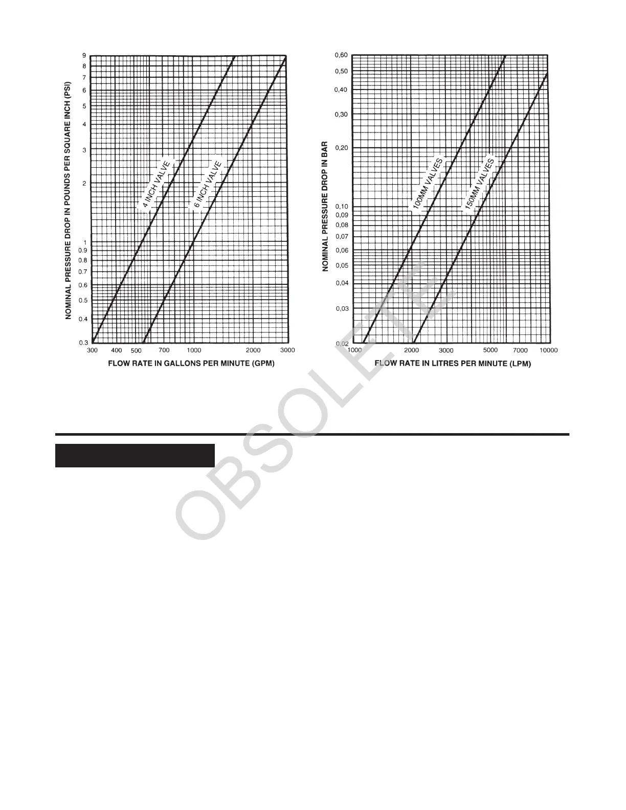
The nominal pressure losses versus
flow are shown in Graphs A-1 and A-2.
The approximate friction losses, based
on the Hazen and Williams formula
and expressed in equivalent length of
Schedule 40 pipe with C = 120, is 12
feet for the 4 inch (100 mm) valve size
and 30 feet for the 6 inch (150 mm)
valve size. The equivalent length of
pipe has been calculated on the basis
of the flow rates typically used with
each size valve.
Valve Trim:
The Wet Pilot Actuation Trim, Dry Pilot
Actuation Trim, or Electric Actuation
Trim illustrated in Figure D form a part
of the laboratory listings and approval
of the F470H Valves and are neces-
sary for their proper operation. Each
package of trim includes the following
items:
• Water Supply Pressure Gauge
• Diaphragm Chamber
Pressure Gauge
• DiaphragmChamber Connections
• Actuation Devices (as applicable)
• Main Drain Valve
• Alarm Test Valve
• Alarm Control Valve
• Automatic Drain Valve
• Dry Pilot Line Pressure Gauge
(as applicable)
Wet Pilot Actuation
(Figure D, Items 1 through 38)
The Wet Pilot Actuation Trim provides
for connection of a detection system
consisting of wet pilot sprinklers (heat
detectors) and manual control stations
-3
GRAPHS A-1 and A-2
NOMINAL PRESSURE LOSS VERSUS FLOW
GRAPH A-1 GRAPH A-2
 Loading...


