10
6(/),163(&7,212)7+(,167$//$7,21
To check the installation:
1. Turn power on at the Circuit reaker ox.
2. Check that the control panel lights up.
3. Start the heater (see User uide).
4. Check that all three tubular elements start to heat up (go
red).
lease keep these instructions.
In the event of problems, please contact the retailer where you purchased
the euipment.
This publication many not be reproduced, in part or in whole, without
the written permission of Tyl. Tyl reserves the right to make changes to
materials, construction and design.
1234Pin:
Pos 1.
NTC
Pin 1:
Pin 2: NTC
Pin 3: NTC
Pin 4:
Pos 2.
Ext sw
Pin 1:
Pin 2: LED
Pin 3: SW
Pin 4: 12 V
Pos 6-9.
4x RS485
Pin 1: A
Pin 2: B
Pin 3: 12 V
Pin 4: GND
Pos 3.
Door sw
Pin 1:
Pin 2: LED
Pin 3: SW
Pin 4: 12 V
Pos 4.
Bim/NTC
Pin 1: Bim
Pin 2: NTC
Pin 3: NTC
Pin 4: Bim
Pos 5.
Addon (option)
1234Pin:
10
11
12
6789
34 5
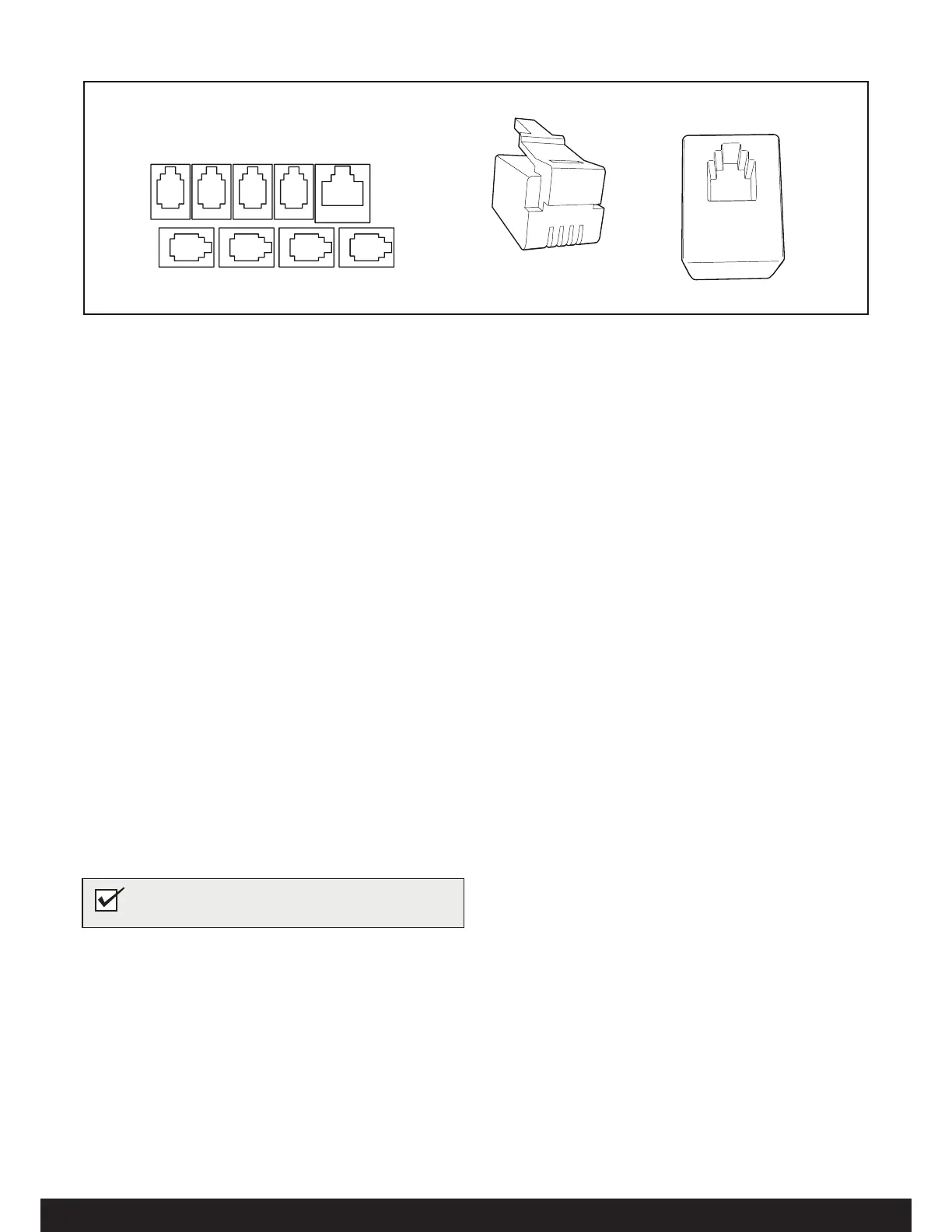
'HVFULSWLRQRIFDEOLQJPRGXODUFRQWDFWV
Figure 21: Modular contacts, description (Pos 1-4 and 6-9: RJ10, Pos 5: RJ45)
2. Ext switch (External switch Optional)
3. N/A
4. N/A
5. N/A
6. Sensor (humidity- and temperature) - Combi Elite.
7. N/A
. N/A
9. Controls panels (Elite).
10. Modular plug (10)11. Modular contact (10)
NOTE! Crimp pliers are needed if changing modular
cabling, e.g. shortening wires.
 Loading...