9
&211(&7,21:,5,1*',$*5$0
TA 20 1 hase 240 1 hase
Model Amperage
Amps
Output
kW
Wire Sie
AW
Amperage
Amps
Output
kW
Wire Sie
AW
Sense Combi-U 7 26 5,3 10 30 7,0
Sense Combi-U 30 6,3 35 ,3
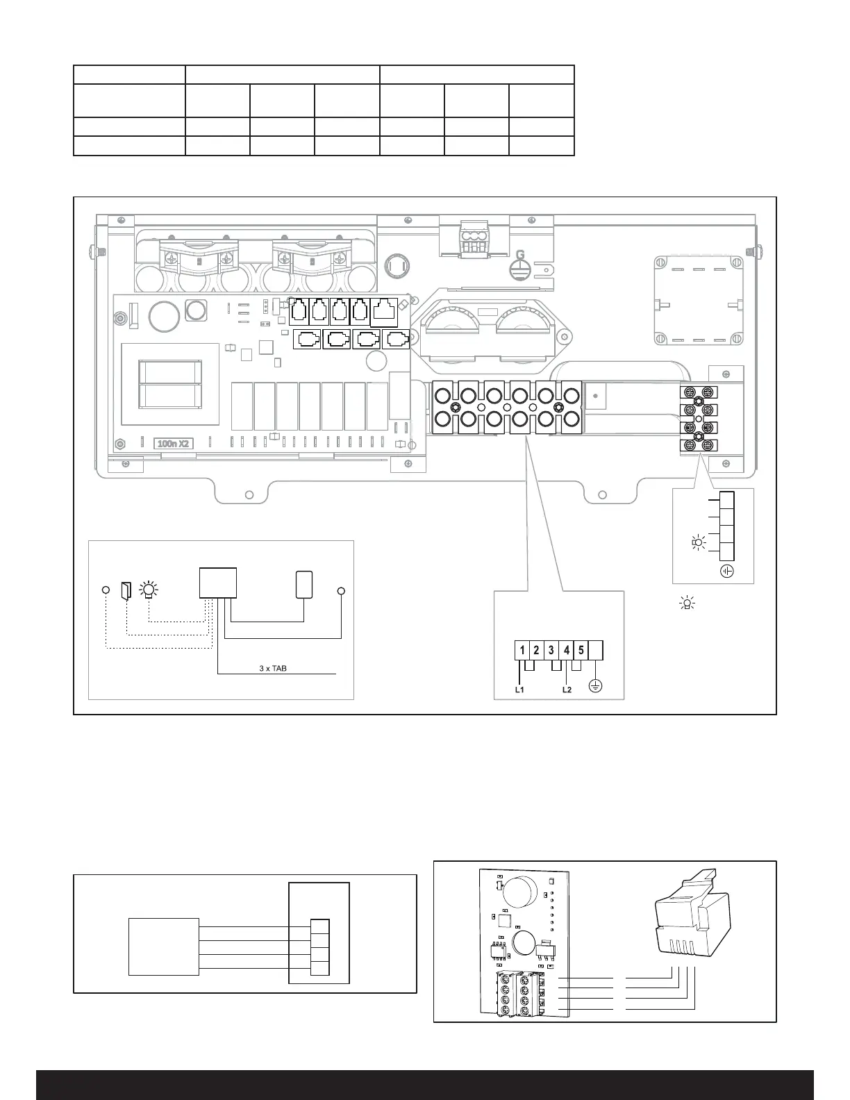
Figure 19: Wiring diagram
1RWH: Heating elments do not change for voltage changes. The heater output will changed based on the voltage applied to heater.
2. Ext switch (External switch Optional)
3. N/A
4. N/A
5. N/A
6. Sensor (humidity- and temperature) - Combi Elite.
7. N/A
. N/A
9. Controls panels (Elite).
10. Heater
11. Terminal for connection of electrical cable
12. Control panel (connect to positions 6-9)
13. Humidity- and temperature sensor - Combi Elite
(connect to positions 6-9)
14. ight/terminal for connection of light
15. Door contact (option)
16. External switch (option)
10
141516
12
13
11
14
RJ10 4P4C
3 x 14 AWG
RJ10 4P4C
RJ10 4P4C
RJ10 4P4C
max 75 feet - Combi Elite
max 300 feet - Combi Pure
*
**
*
**
BB4140
12
6789
34 5
120 V~
14 AWG
Max. 6 Amp.
5,3-8,3 kW
208/240 V~
G
Fig 20a: Connecting the humidity- and temperature sensor -
Combi Elite
1. Modular plug (10, see Fig 19)
2. Humidity- and temperature sensor
A
B
11
12
1:A
2:B
Pin
3:12V
4:GND
1
2
Fig 20b: Connecting the humidity- and temperature sensor -
Combi Elite
ed, reen, WWhite, lack
A
B
11
12
1234
R
G
W
B
 Loading...