3
,167$//$7,21*8,'(
%()25(,167$//$7,21
3DUWV
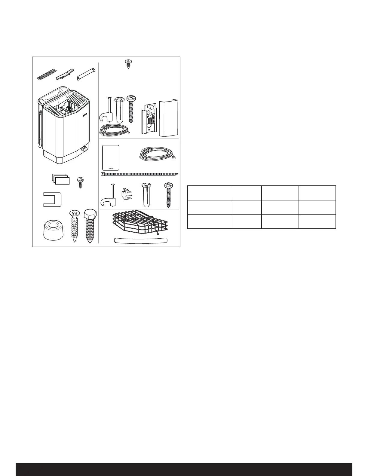
Check that the following parts are included in the packaging:
Figure 1: Sauna heater/control panel parts
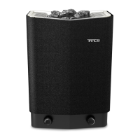
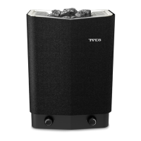
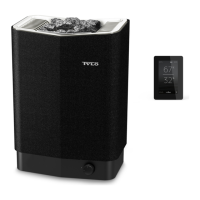
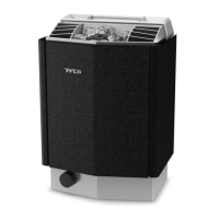
1. Sauna heater
2. Herb bowl/air humidi er
3. Herb bowl
4. rackets
5. Warning and Caution plates for the room in multiple languages
6. Screws 4 x 6.5 x 6 for Warning and Caution plates
7. Connectors x 3
. Spacers x 4
9. Screws x 4
10. racket screws x 2
12. Screw 4x6,5 (x 1 Combi ure) (x 2 Combi Elite)
13. Sensor cover (Combi ure)
14. Clips TC (3-5) x 10 pieces
15. lastic plugs 25x5 x 2 pcs
16. Screws 6x25 x 2 pcs
17. Humidity- and temperature sensor with cover (Combi Elite)
1. Cable between heater and humidity- and temperature sensor,
10 44C, cable length 4 m x 1 pce (Combi Elite)
19. Control panel (Elite Wi)
20. Cable between heater and control panel, 10 44C, cable
length 5 m x 1 pce
21. Cable tie
22. Clips C 3x5 x 10 pieces
23. Modular plug 4, 4/410 x 2
24. lastic plugs 25x5 x 3 pcs
25. Screws 6x25 x 3 pcs
26. ock guard
27. rotection hose 14x150 mm x 3 pcs, for 10 cables (sen-
sor, control panel, door switch)
,QVWDOODWLRQWRROV
The following tools and materials are needed for installation and
connection:
level
tape measure
electric drill
screw drivers
,QVWDOODWLRQSODQQLQJ
efore starting to install your sauna heater:
lan the sauna heater positioning (see the Heater positioning
- normal installation section, page 4).
lan the control panel positioning (see the attached instruc-
tions for the control panel for allowable positioning).
lan the sensor positioning (see Figure 3, page 4).
osition the air intake vent (see the Air intake vent positioning
section, page 5).
osition the air exhaust vent (see the Air exhaust vent posi-
tioning section, page 5).
lan the electrical installation (see the Connection/wiring
diagram section, page 9).
3
2
1
4
10
9
6
7
22
20
23
24
25
26
27
21
5
14
15
16
12
13
17
19
1
Elite
WiFi
Table 1: Voltage and sauna volume
Model oltage Sauna volume
min. cu.ft.
Sauna volume
max. cu.ft.
Sense Combi-U 7
SCU7
20
240
175
175
265
320
Sense Combi-U
SCU
20
240
250
250
360
440
Contact your dealer if anything is missing.
Control panel ure is supplied with Sense Combi ure.
Control panel Elite WiFi is supplied with Sense Combi Elite.
See separate guides.
,QVWDOODWLRQUHTXLUHPHQWV
To ensure safe use of the heater, check that the following criteria
are met:
Electrical wiring should be installed in accordance with NEC
and all state and local codes.
Fuse sie (A) and power cable sie (AW) must be suitable
for the heater (see The section called Connection/wiring
diagram, age 9.
The sauna ventilation must comply with the instructions in
this manual (see The section called ositioning the inlet vent,
age 5, The section called ositioning the outlet vent, age
5).
The position of the sauna heater, control panel, and sensors
must comply with the instructions in this manual.
The heater output (kW) must be suitable for the sauna
volume (cu.ft.) (See Table 1, age 3). The minimum and
maximum volumes must not be exceeded.
NOTE: A FCI device is not reuired by ET. A FCI may
be installed if reuired by local codes. However, FCI devic-
es will tend to nuisance trip during use of the product.
 Loading...