4
1
3
2
4
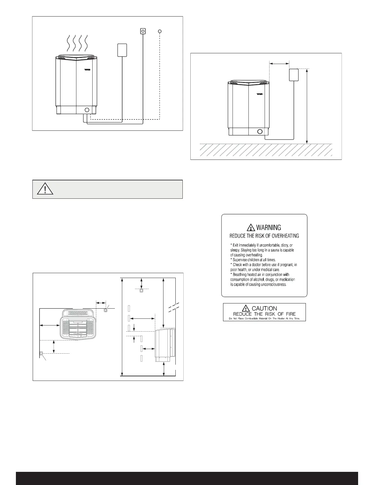
Figure 2: Schematic diagram of installation
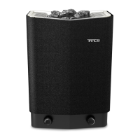
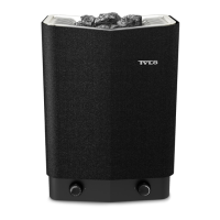
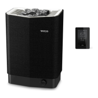
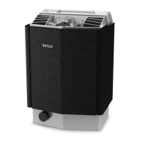
1. Sauna heater
2. Control panel
3. Sensor
4. External on/o switch (option, door contact needed for func-
tion)
3RVLWLRQLQJWKHKHDWHUQRUPDOLQVWDOODWLRQ
osition the sauna heater:
on the same wall as the door (or the side wall if very close to
the door wall).
osition the heater at a safe distance from the oor, side
walls and interior ttings (see Figure 3).
osition the sensor according the picture (see Figure 3).
1
7
10
9
8
11
6
4
3
2
3
5
Figure 3: Positioning the heater - normal installation
1. Minimum distance from side wall: 4 in
2. Sensor position alt 1: 3 in from heater
3. Sensor
4. Sensor position alt 2: 3 in from heater front
5. Sensor position: 1 in from ceiling
6. Minimum distance from ceiling: 44 in
7. Minimum distance from interior ttings: 4 in
. Minimum ceiling height: 75 in
9. Minimum distance: 1 in
10. Minimum distance from interior ttings: 2 in
11. Distance from oor: 7 in
3RVLWLRQLQJWKHFRQWUROSDQHO
The control panel can be installed inside or outside of the sauna
room.
The control panel must be correctly positioned with regard to
safety distances below when installed inside the sauna room
Figure 4: Safety distance, control panel
1. Heater
2. Control panel
3. Max. 36 in
4. Min. 12 in
Figure 5: Warning/Caution plate
1
2
4
3
DANGER! No more than one heater may be instal-
led in the same sauna cabin.
 Loading...