5
6DXQDURRPYHQWLODWLRQ
In a sauna, the air should be changed about 6 times an hour. See
Figure 6.
It is recommended that ventilation openings meet the reuire-
ments of U Speci cation 75. The minimum opening should be
determined using one of the following formulas:
For 31, 9 .3
For 31, 0.3
where the oor area of the room in suare feet and
the minimum vent sie in suare inches
Exampleenting Calculation:
oom is 54 s.ft.(9 ft. by 6 ft.) 54 is larger than 31.
Multiple 54 x 0.3 16.2 s. in.
ent sie opening should be 4 in x 4 in.
3RVLWLRQLQJWKHLQOHWYHQW
Install the inlet vent straight through the wall under the centerline
of the heater.
Figure 6: Positioning the air intake and exhaust vents
1. Inlet vent position.
2. Outlet vent position through the sauna wall.
3. Outlet vent position through the cavity.
4. Outlet vent position via duct.
3RVLWLRQLQJWKHRXWOHWYHQW
osition the outlet vent
at the maximum possible distance from the air intake vent,
e.g. diagonally (see Figure 6).
high on the wall or in the ceiling (see Figure 6).
so that it vents into the space that the door and air intake
vent open into.
The outlet vent must have the same area as the inlet vent.
Ensure that the outlet vent is open.
Mechanical ventilation is not recommended due to the risk of poor
air exchange, which can negatively a ect the heater temperature
cut-out.
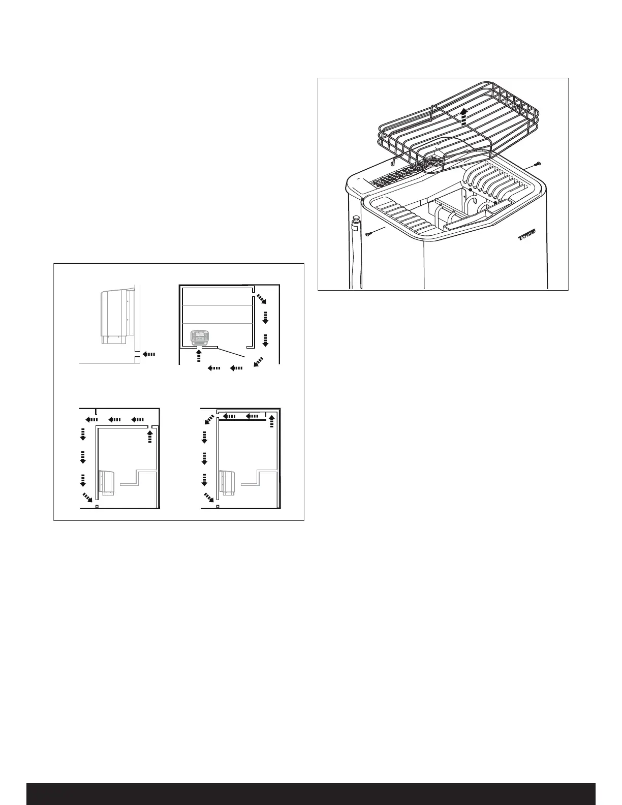
5HPRYLQJWKH5RFN*XDUG
Unscrew the two screws on the side of the heater and lift the
rock guard upwards, see Figure 7. (This is necessary when lling
the stone compartment or cleaning the fragrance holder and air
humidi er).
1 2
34
Figure 7: Removing the Rock Guard
5RRPFRQVWUXFWLRQ
For safety and reliability, the following rules must be addressed.
The enclosed WANIN: educe the risk of overheating
warning plate must be mounted on or alongside the door
outside the sauna room at about eye level. Use the supplied
screws.
The enclosed CAUTION: educe the risk of re caution
plate must be mounted on the interior wall above the heater.
Use the supplied screws.
No permanent locking or latch system is to be used on the
sauna door.
Acceptable door ttings are: magnetic catches, friction catch-
es, spring or gravity loaded closures. The door must always
open outwards.
No shower may be installed in a sauna room.
No electrical receptacle shall be installed inside the sauna
room.
The heater should not be operated without its container prop-
erly lled with rocks and the rock guard in place.
If an intercom speaker is installed, it should be away from the
heater and as close to the oor as possible.
If a room light is installed, it should be a surface mounted
bracket type. Wall mounted lights should be about 70” above
the oor. Ceiling mounted lights should be of an approved
type with a junction box that is remote to the xture itself.
Use only a xture that uses A.F. or xture type internal wiring.
A 60 watt bulb should provide su cient lighting.
Fire sprinkler systems installed inside any sauna room should
be properly rated for sauna room temperatures.
Always mount the heater according to these installation
instructions.
 Loading...