6
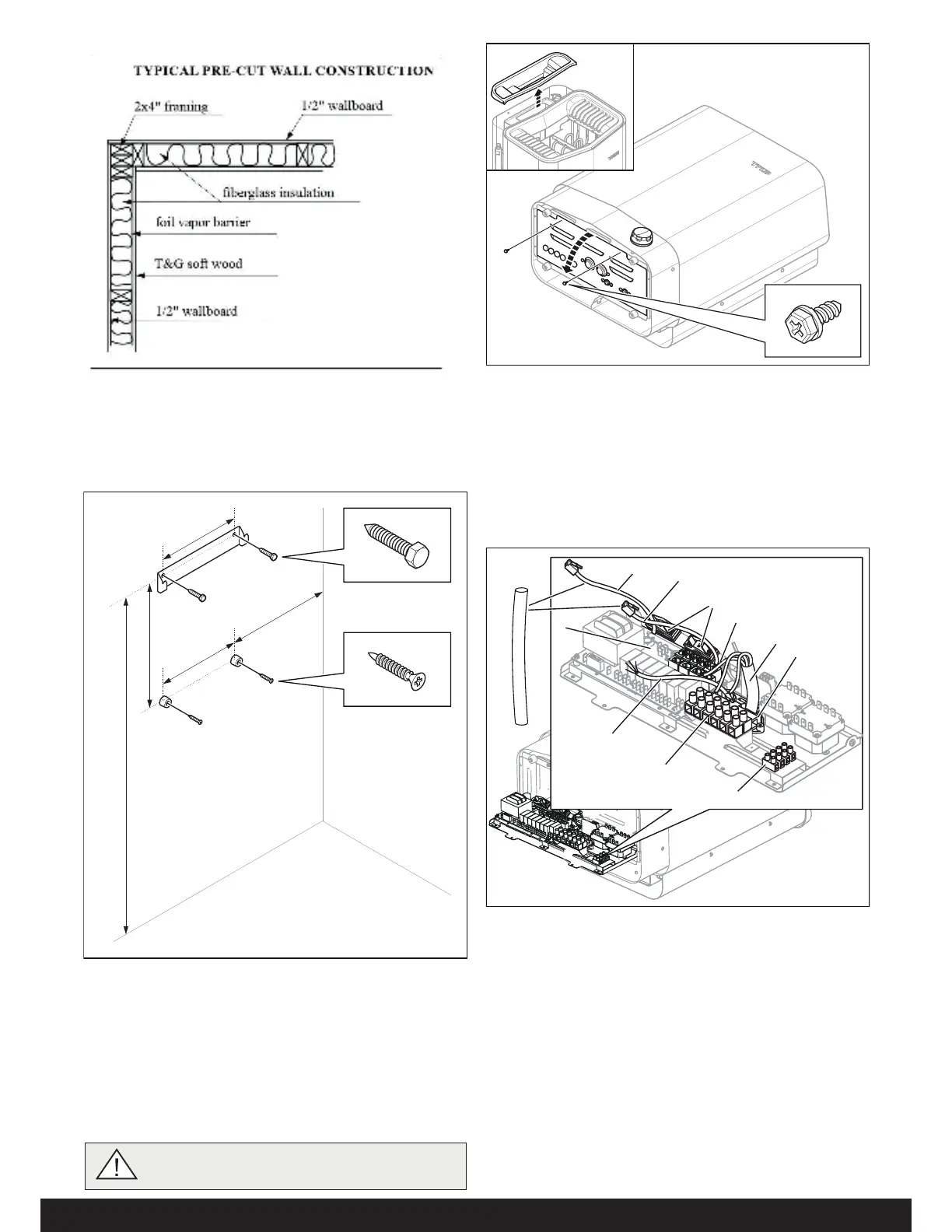
Figure 10: Opening/closing the cover
Figure 8: Typical wall construction
Connect the heater using standard wiring (Fk or E) approved
for xed installation.
Any single wires (Fk) must be protected in electrical conduits ()
to the heater.
4. Connect the main supply electrical cable (1) to the terminal
(2) (see Figure 11) according to the wiring diagram (see the
Connection/wiring diagram section, page 9).
It is easiest to prepare for installation with the heater lying down.
To install the heater:
2. emove the cover to the water reservoir and lay the heater
down with the front facing upwards (see Figure 10).
3. Undo the screws and open the cover (see Figure 10).
WARNING! Always check that the heater is con-
nected to the correct main/phase voltage!
5. un the cables for the control panel and the temperature
sensor through the cable grommets (3). Connect the control
panel cable (4) to one of the four S45 contacts (positions
6-9) (see Figure 11) according to the wiring diagram (see the
Connection/wiring diagram section, page 9 g.19).
6. Connect the humidity- and temperature sensors cable (6) to
one of the four S45 contacts (positions 6-9) (5) according
to the wiring diagram (see the Connection/wiring diagram
section, page 9 g. 19).
2
4
5
7
6
9
1
10
3
11
Figure 11: Circuit board
1. Electrical cable
2. Terminal for connection of elec-
trical cable
3. Cable grommet (x6)
4. Control panel cable
5. Modular contacts for connection
of control panel, sensor etc.
6. Sensor cable
7. ight cable (if connected)
. Terminal for connection of
light (if connected)
9. Strain relief connector for
cables to modular contacts
(x2)
10. Strain relief connector for
electrical cable
11. rotection hose for 10
cables
,167$//$7,21
6DXQDKHDWHULQVWDOODWLRQ
1. Attach the bracket and spacers to the wall following the speci-
ed dimensioning (see Figure 9). -
Figure 9: Bracket with screws and spacers
1. 26.3 in
2. 1
1.0 in
3. 7.3
in
4.
9.0 in (minimum distance)
1
2
3
3
4
7\SLFDOZDOOFRQVWUXFWLRQ
 Loading...