9
PRIOR TO INSTALLATION
Parts
Checkthatthefollowingpartsareincludedinthepackage:
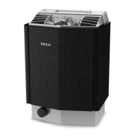
Figure 1: Sauna heater parts
1. Sauna heater
2. Brackets x 1 pcs
3. Warningstickerintwelvelanguages(axthestickerinyour
language to the front of the heater)
4. Bracket screws x 2 pcs
5. Spacers x 2 pcs
6. Screws x 4 pcs
7. Herb grille x 1 psc
8. Connector x 1 pcs
9. Drainage hose with stopper x 1 pcs
10. Hose clips x 2 pcs
11. Strain relief device x 1
12. Temperature sensor holder x 2 pcs
13. Coverprolex2pcs
14. Capillary tube clips x 12 pcs
15. Brad nails x 12 pcs
16. Screws x 2 pcs
17. Float x 1 pcs
Contact your dealer if any parts are missing.
Installation requirements
To ensure safe use of the heater, check that the following criteria
aremet:
• The cable (EKK) or electrical ducting (Fk) for connecting the
heater must be run on the outside of the heat insulation.
• The cables must be run correctly (see the Connection/wiring
diagramsection,gure19).
• The fuse size (A) and the power cable size (mm²) must be
suitable for the heater (see the Connection/wiring diagram
section,gure19).
• The sauna ventilation must comply with the instructions in this
manual(seetheAirintakevalvepositioningsection,gure4,
andtheAirexhaustvalvepositioningsection,gure4).
• The position of the sauna heater must comply with the instru-
ctions in this manual.
• The heater's output (kW) must be adapted to the sauna's
volume (m³) (see Table 1). The minimum and maximum
volumes must not be exceeded.
Table 1: Output and sauna volume
Output kW Sauna volume min./max. m³
4.5 2 - 4
NOTE! A stone/tile/glass wall without heat insulation
will increase the warm-up time. Each square metre of
hard ceiling or wall surface equals an additional
1.2–2 m³ of sauna volume.
Installation tools
The following tools and materials are needed for installation and
connection:
• water level
• adjustable spanner
• electric drill
• screwdrivers
Installation planning
Beforestartingtoinstallyoursaunaheater:
• Plan the sauna heater positioning (see the Heater positioning
- normal installation section).
• Position the air intake vent (see the Air intake vent positioning
section,gure4).
• Position the air exhaust vent (see the Air exhaust vent posi-
tioningsection,gure4).
• Plan the electrical installation (see the Connection/wiring
diagramsection,gure19).
Heater positioning - normal installation
Positionthesaunaheater:
• on the same wall as the door (in exceptional cases it can be
installed on the side wall, provided it is very close to the wall
with the door). The heater may also be installed in a recess
(see Figure 3).
• Positiontheheateratasafedistancefromtheoor,side
wallsandinteriorttings(seeFigure2).
DANGER! No more than one heater may be instal-
led in the same sauna cabin.
Figure 2: Heater positioning - normal installation
1. Minimumdistancetosidewall:20mm
2. Minimumdistancetoceiling:1250mm
3. Minimumdistancetointeriorttings:30mm
4. Minimumceilingheight:1900mm(max2100mm)
5. Minimumdistance:10mm
6. Minimumdistancetointeriorttings:10mm
7. Distancefromoor:170mm
DANGER! Poor ventilation or heater positioning
may lead to dry distillation, posing a re risk
under certain circumstances.
DANGER! Insucient insulation of the sauna
cabin may pose a re risk.
DANGER! Use of the wrong materials in the
sauna cabin, such as particle board, drywall, etc.,
may pose a re risk.
DANGER! The heater must be connected by a quali-
ed electrician pursuant to applicable regulations.

 Loading...