10
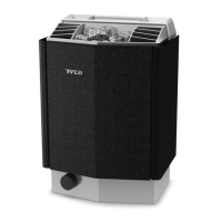
Heater positioning - recess installation
Positiontheheateratasafedistancefromtheoor,sidewalls
andinteriorttings(seeFigure3).
Figure 3: Heater positioning - recess installation (minimum
permitted volume 4 m³)
1. Minimumdistancetosidewall:200mm
2. Max. 1000 mm
3. Minimumdistancetoceiling:1250mm
4. Minimumdistancetointeriorttings:30mm
5. Minimumceilingheight:1900mm(max2100mm)
6. Minimumdistance:10mm
7. Minimumdistancetointeriorttings:10mm
8. Distancefromoor:170mm
Air intake vent positioning
Install the air intake vent straight through the wall under the
centreline of the heater.
Vent size for a family sauna approx. 125 cm².
The air circulation from the door must concord with the hot air
circulation from the heater.
Figure 4: Air intake and exhaust vent positioning
1. Air intake vent positioning.
2. Air exhaust vent positioning through the sauna wall.
3. Air exhaust vent positioning through the cavity.
4. Air exhaust vent positioning via duct.
Air exhaust vent positioning
Positiontheairexhaustvent:
• at the maximum possible distance from the air intake vent,
e.g. diagonally (see Figure 4).
• high on the wall or on the ceiling (see Figure 4).
• so that it vents into the space that the door and air intake
vent open into.
The air exhaust vent must have the same area as the air intake vent.
Make sure that the air exhaust vent is open.
Mechanical ventilation is not recommended due to risk of poor air ex-
change,whichmaynegativelyaecttheheatertemperaturecut-out.
INSTALLATION
Sauna heater installation
It is easiest to prepare for installation with the heater lying down.
Toinstalltheheater:
1. Remove the cover on the water reservoir and lay the heater
down with the front facing upwards (see Figure 5).
2. Undo the screws and open the cover (see Figure 5).
Figure 5: Opening/closing the cover
Connect the heater using standard wiring (Fk or EKK) approved
forxedinstallation.
Any single wires (Fk) must be protected in electrical conduits (VP)
up to the heater.
3. Attach strain relief devices (3) and connect the electrical
cable (1) to the terminal (2) (see Figure 6) according to the
wiring diagram (see the Connection/wiring diagram section,
g19).
WARNING! Always check that the heater is con-
nected to the correct mains/phase voltage.
DANGER! The air exhaust vent must not lead out-
doors. This could cause the ventilation direction
to be reversed, which may negatively aect the
heater temperature cut-out.
DANGER! If there is a cavity above the sauna cei-
ling, it must not be sealed without leaving at least
one vent hole on the same wall as the sauna door.

 Loading...