22
33
44
20 ~3020 ~30
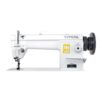
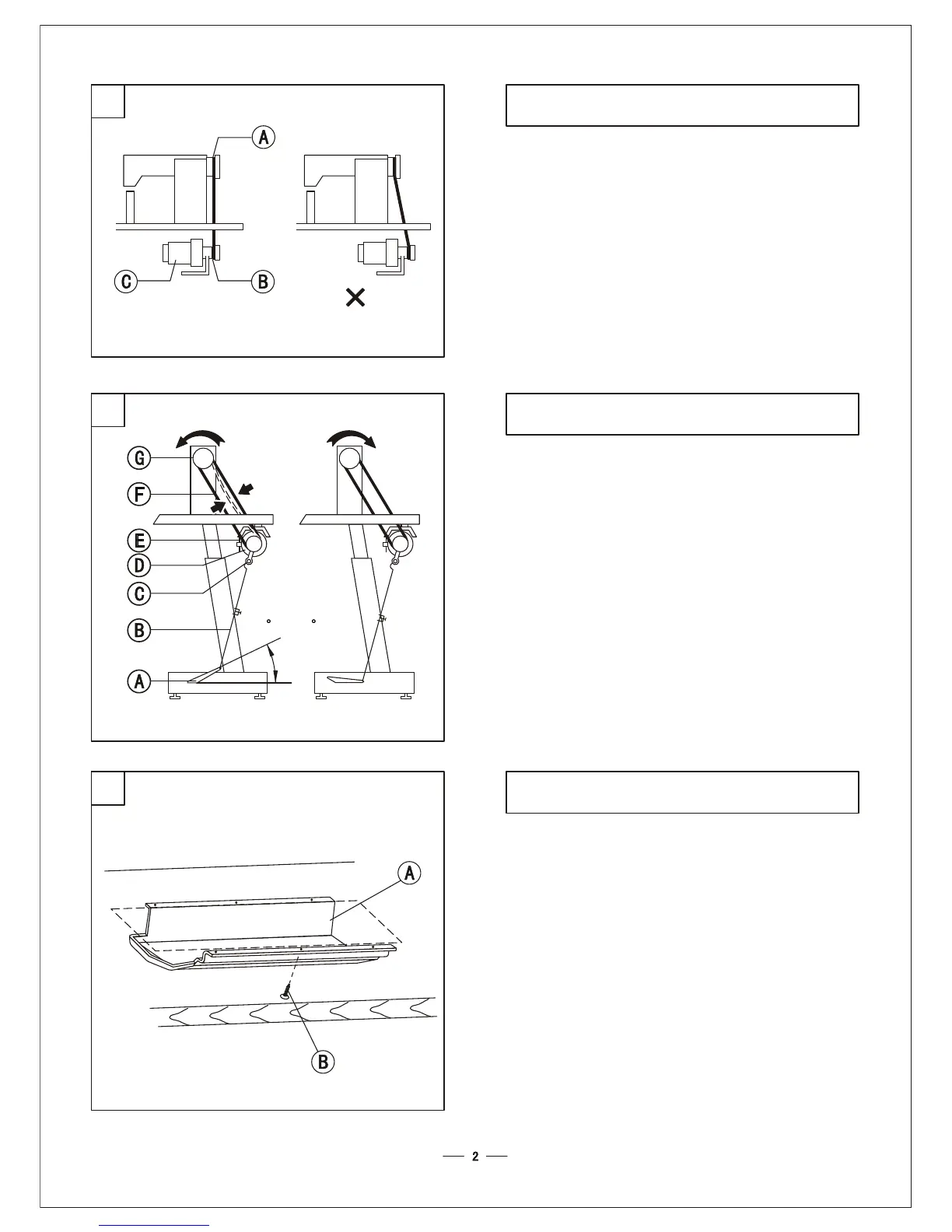
5. Installing the motor (Fig.2)5. Installing the motor (Fig.2)
Align the balance wheel belt groove A with motor
pulley belt groove B by moving the motor C
leftward and rightward. Make sure the belt does not
touch the table.
Align the balance wheel belt groove A with motor
pulley belt groove B by moving the motor C
leftward and rightward. Make sure the belt does not
touch the table.
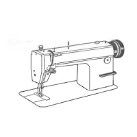
6. Connecting pedal to the clutch lever (Fig.3)6. Connecting pedal to the clutch lever (Fig.3)
1. The optimum tilt angle of pedal with floor is approx..
15 degree.
2. Adjust the motor clutch so that the clutch lever C
and draw bar B run in line as Fig.3.
3. The machine balance wheel should rotate counter
clockwise for normal sewing when view from
opposite side of the balance wheel.The motor rotates
in the same direction. And the rotation can be
reversed by reversing (turn over 180deg.) the plug
of the motor.
4. Adjust the tension of the V-belt by moving the motor
vertically. The proper tension of the V-belt is a slack
of 10-12mm when the belt is depressed (on the belt
pan) by finger.
1. The optimum tilt angle of pedal with floor is approx..
15 degree.
2. Adjust the motor clutch so that the clutch lever C
and draw bar B run in line as Fig.3.
3. The machine balance wheel should rotate counter
clockwise for normal sewing when view from
posite side of the balance wheel.The motor rotates
in the same direction. And the rotation can be
reversed by reversing (turn over 180deg.) the plug
of the motor.
4. Adjust the tension of the V-belt by moving the
vertically. The proper tension of the V-belt is a slack
of 10-12mm when the belt is depressed (on the belt
pan) by finger.
op
motor
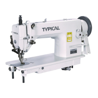
7. Installing the oil reservoir (Fig.4)7. Installing the oil reservoir (Fig.4)
Smoothly put the oil reservoir A into the bottom of
the table, and tighten the screw B into the both sides
of the table cutout to secure the oil reservoir. Please
note the position of knee lifter.
Smoothly put the oil reservoir A into the bottom of
the table, and tighten the screw B into the both sides
of the table cutout to secure the oil reservoir. Please
note the position of knee lifter.