2
1
2
1
119.5
15
30
A
B
3
3. Installation and preparation
3.1 Installation
3.1.1 Location of the machine
To ensure a smooth running, the machine
of rubber mat between machine stand and floor is
recommended for further reducing the running
noise and vibration.
Should be located on rigid and flat floor.The insert
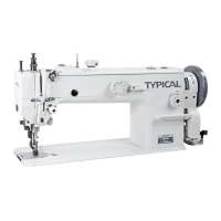
3.1.2 Installing drip pan(Fig.1)
Fix drip pan 1into the table cutout, aligning
rod 15 of machine head, and to touch it, also
maintain dimendions 30 and 119.5mm from nail
hole to the table, then drive nails into both
sides of the cutout to secure the drip pan.(further
see figure on page56).
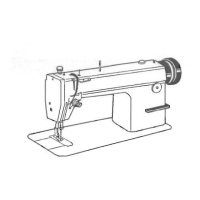
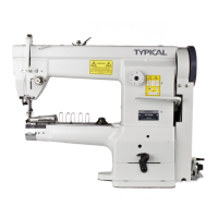
3.1.3 Mounting machine head(Fig.2)
Make the hinge A of machine head engaged
with hinge socket B on the table, then turn the
machine head freely till it is seated on the frame
of table cutout.
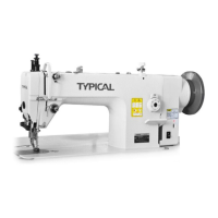
knee lifter lifting rod 3 with knee lifter connecting
3
268
132.5
119.5
15
3
11
29
6
7
18
3.1.4 Mounting rock shaft bracket of knee liter
(Fig.3, also see figure on page 56)
1) Adjust rock shaft knee plate 18 according to
the body of operator,for the convenience to operate.
2) Adjust the position of knee lifter assembly
according to Fig. 3, then fasten the rock shaft
bracket with wood screws 6.