LEA-6 / NEO-6 - Hardware Integration Manual
GPS.G6-HW-09007-A Preliminary Hardware description
Page 12 of 62
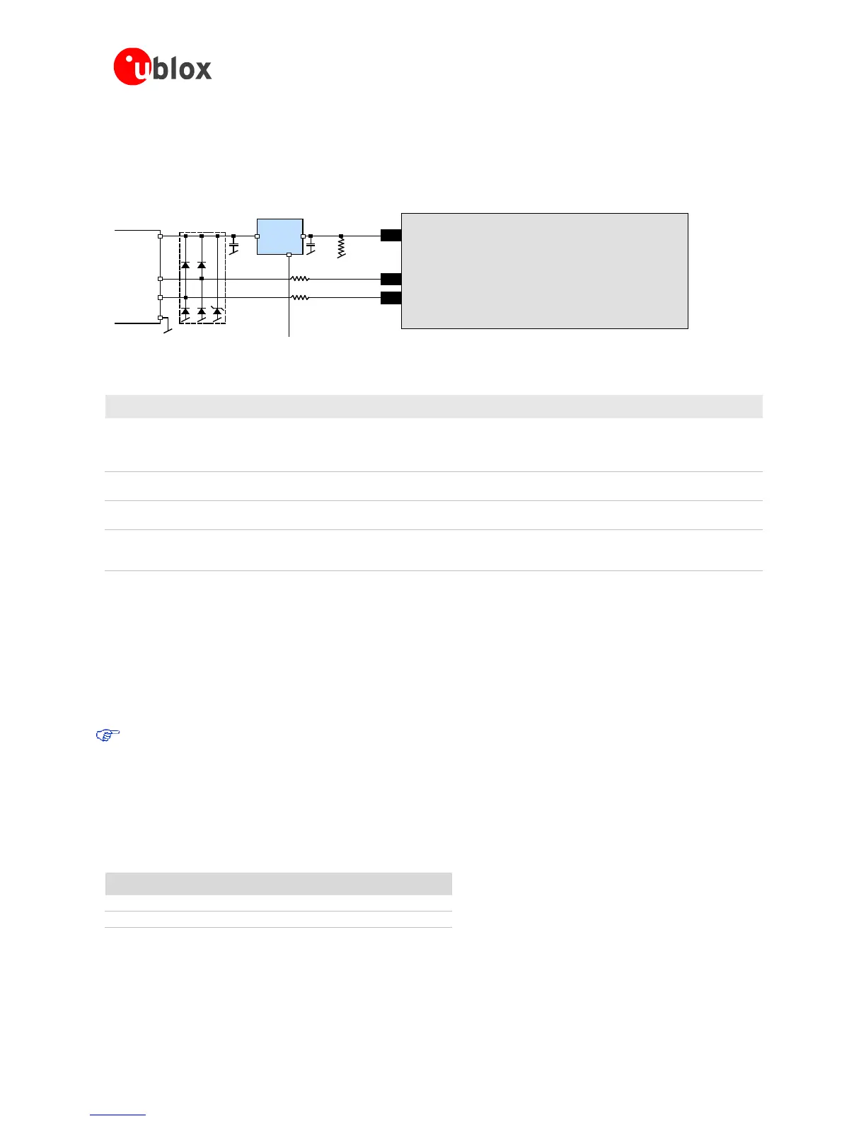
enable signal (EN) of the VCC-LDO or the output of a voltage supervisor. Depending on the characteristics of the
LDO (U1) it is recommended to add a pull-down resistor (R11) at its output to ensure VDD_USB is not floating if
LDO (U1) is disabled or the USB cable is not connected i.e. VBUS is not supplied.
If the device is bus-powered, LDO (U1) does not need an enable control.
self-powered device, but if bus-powered LDO (U1) must be able to deliver the
maximum current of ~150 mA. A low-cost DC/DC converter such as LTC3410
from Linear Technology may be used as an alternative.
C23,
C24
Capacitors Required according to the specification of LDO U1
D2 Protection
diodes
Protect circuit from overvoltage
/ ESD when connecting.
Use low capacitance ESD protection such as ST Microelectronics USBLC6-2.
R4, R5 Serial
termination
resistors
Establish a full-speed driver
impedance of 28…44 Ohms
A value of 22 Ohms is recommended.
R11 Resistor 10k R is recommended for USB self-powered setup. For bus-powered setup
R11 can be ignored.
Table 1: Summary of USB external components
1.6.3 Display Data Channel (DDC)
An I
2
C compatible Display Data Channel (DDC) interface is available with LEA-6 and NEO-6 modules for serial
communication. For more information about DDC implementation refer to the u-blox 6 Receiver Description
including Protocol Specification [3]. Background information about the DDC interface is available in Appendix
C.1.
u-blox 6 GPS receivers normally run in I
2
C slave mode. Master Mode is only supported when external
EEPROM is used to store configuration. No other nodes may be connected to the bus. In this case, the
receiver attempts to establish presence of such a non-volatile memory component by writing and reading
from a specific location.
Pins SDA2 and SCL2 have internal 13kOhm pull-ups. If capacitive bus load is very large, additional external pull-
ups may be needed in order to reduce the pull-up resistance.
Table 2 lists the maximum total pull-up resistor values for the DDC interface. For small loads, e.g. if just
connecting to an external EEPROM, these built-in pull-ups are sufficient.
Load Capacitance Pull-Up Resistor Value R20, R21
50 pF N/A
100 pF
18 kΩ
250 pF
4.7 kΩ
Table 2: Pull-up resistor values for DDC interface

 Loading...

