LEA-6 / NEO-6 - Hardware Integration Manual
GPS.G6-HW-09007-A Preliminary Product handling
Page 44 of 62
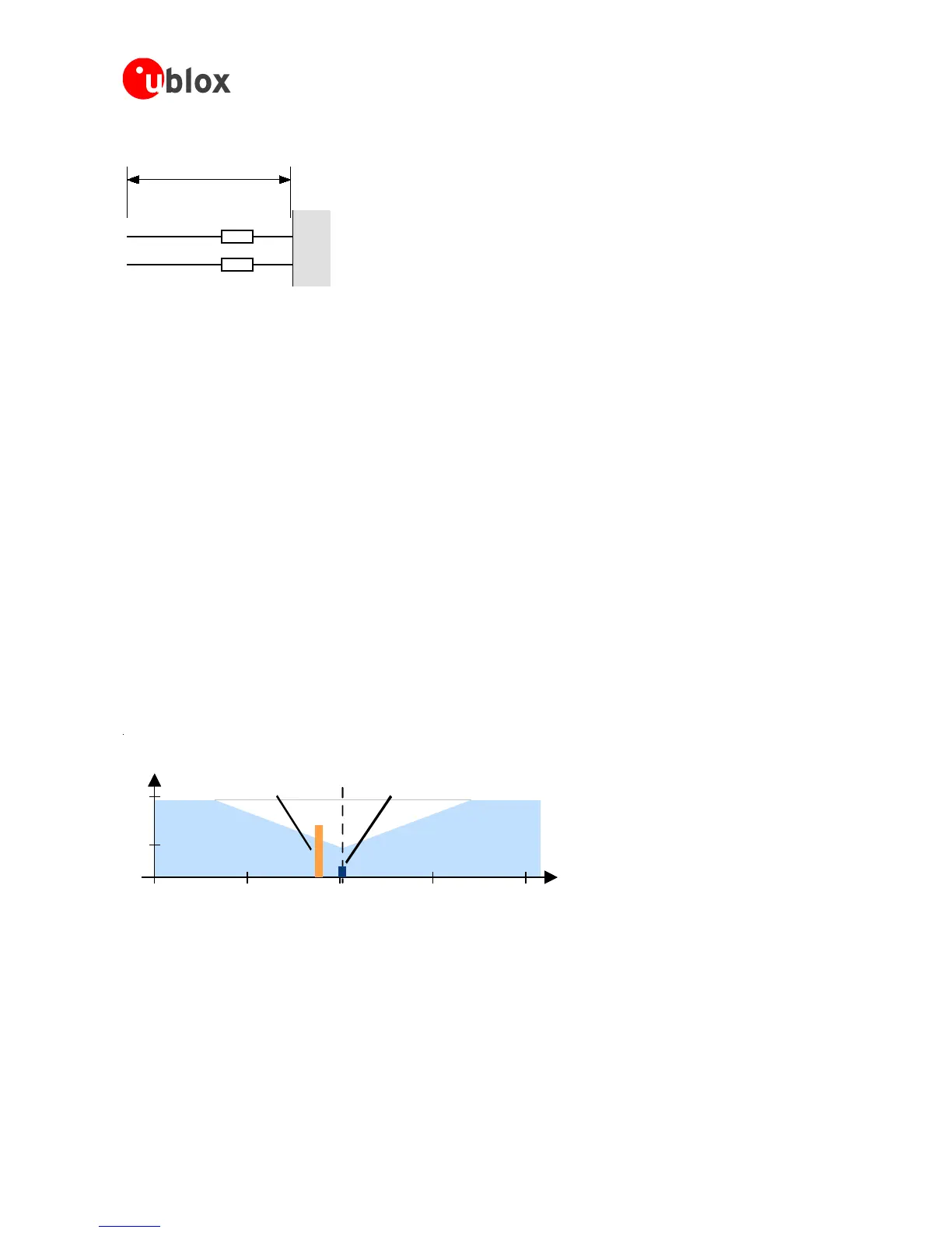
Example of EMI protection measures on the RX/TX line using a ferrite bead:
Figure 35: EMI Precautions
VCC can be protected using a feed thru capacitor. For electromagnetic compatibility (EMC) of the RF_IN pin refer
to section 3.3.6
3.3.8 GSM applications
GSM uses power levels up to 2W (+33dBm). The absolute maximum power input at the GPS receiver is -5dBm
for Antaris-4 and u-blox 6 GPS receivers.
3.3.8.1 Isolation between GPS and GSM antenna
For GSM applications plan a minimum isolation of 40dB. In a handheld type design an isolation of approximately
20dB can be reached with careful placement of the antennas, but this isn’t sufficient. In such applications an
additional input filter is needed on the GPS side to block the high energy emitted by the GSM transmitter.
Examples of these kinds of filters would be the SAW Filters from Epcos (B9444 or B7839) or Murata.
3.3.8.2 Increasing jamming immunity
Jamming signals come from in-band and out-band frequency sources.
3.3.8.3 In-band jamming
With in-band jamming the signal frequency is very close to the GPS frequency of 1575 MHz (see Figure 36). Such
jamming signals are typically caused by harmonics from displays, micro-controller, bus systems, etc.

 Loading...

